Understanding and Using the Statistics of Communication Signals
CSP Estimators: The Strip Spectral Correlation Analyzer
The SSCA is a good tool for blind (no prior information) exhaustive (all cycle frequencies) spectral correlation analysis. An alternative is the FFT accumulation method.
In this post I present a very useful blind cycle-frequency estimator known in the literature as the strip spectral correlation analyzer (SSCA) (The Literature [R3-R5]). We’ve covered the basics of the frequency-smoothing method (FSM) and the time-smoothing method (TSM) of estimating the spectral correlation function (SCF) in previous posts. The TSM and FSM are efficient estimators of the SCF when it is desired to estimate it for one or a few cycle frequencies (CFs). The SSCA, on the other hand, is efficient when we want to estimate the SCF for all CFs.
The SSCA is a kind of time-smoothing method and a detailed examination of the method and its properties can be found in The Literature [R3-R5]. Here I’ll briefly describe the estimator mathematically, then try to explain why the rather odd-looking estimator form produces estimates of the spectral correlation function. Finally, I’ll provide a few processing examples. In future posts I’ll contrast the SSCA performance and computational cost with those for the FSM and TSM.
The block diagram for the SSCA looks like this:
Figure 1. A high-level block diagram for the strip spectral correlation analyzer (SSCA) method of exhaustive spectral correlation function (SCF) estimation. The SSCA produces point estimates of the SCF with resolution in frequency of and resolution in cycle frequency of . The spacing of the estimates is such that no significant slice (fixed cycle frequency, variable frequency) is missed.
Essentially, the input data is first channelized, and then each of the narrowband outputs of the channelizer is multiplied by the original input signal and Fourier transformed. The channelizer is usually implemented by a sliding FFT. So the method clearly harnesses the computational power and efficiency of the FFT, leading to its overall low cost compared to other exhaustive-CF spectral correlation estimators (such as the FSM and TSM when they are placed in a loop over cycle frequency).
Mathematically, a particular cross (between arbitrary signals and ) spectral correlation function point estimate is given by
where the demodulates are defined as
Here we use the subscript to denote the total averaging time in seconds, so that , where is the sampling rate. And this notational choice connects well to other CSP Blog posts’ notations. Similarly, the subscript denotes the length of time used in each of the channelizer’s FFTs, so that . But we don’t really care about the absolute value of , so the time-referencing subscripts aren’t so important going forward.
Let’s try to show that the SSCA point-estimate expression (1) can be manipulated into a form such that we can more easily see that the spectral correlation function is estimated. The first step is to substitute the expression for the demodulate into the SSCA point estimate and simplify,
Define . Then
Now, substitute , rename to , substitute , and finally rename to :
Assume that . The inner sum is just an estimate of the cyclic autocorrelation, with data tapering (windowing) and with limits on the sum that depend on the lag . This is the cyclic correlogram (The Literature [R5]). Thus, we have the following relation,
Here we can identify the pair from our usual parameterization of the spectral correlation function. First, we have . The spectral frequency is the argument of , and is given by .
Therefore, the point estimate is confirmed. We see that the time-smoothed SSCA estimate is approximately equal to a Fourier-transformed cyclic autocorrelation estimate. The requirement for reliability on this estimate is that the length of time used to estimate the cyclic correlogram, , is sufficiently large and much larger than the approximate span of the function, which is contained in the window , which itself has width . That is, or once again.
The demodulates are formed by short-duration () FFTs, which are often called the channelizer FFTs, and the final point-estimate outputs are formed by long () FFTs, which are often called the strip FFTs, because each one of those FFTs produces a set of point estimates that lie on strip parallel to the line in the plane.
Numerical Example: Rectangular-Pulse BPSK
Let’s turn to our usual example: the textbook rectangular-pulse BPSK signal. This signal has normalized bit rate of and normalized carrier frequency of . The non-conjugate cycle frequencies are harmonics of the bit rate, and so are equal to , and the conjugate cycle frequencies are the non-conjugate cycle frequencies plus the doubled carrier .
We process samples of the rectangular-pulse signal using a straightforward C-language implementation of the SSCA. The number of strips, , is set to . This SSCA processing results in SCF point estimates for the non-conjugate SCF and another for the conjugate SCF. However, symmetries allow us to look at the non-conjugate function for only the non-negative cycle frequencies. Nevertheless, there are a lot of point estimates in the example. Plotting all of them is a difficult exercise in visualization. Here I plot only the pairs that correspond to the largest values of spectral correlation magnitude:
Figure 2. Positions of the largest 500 point estimates (non-conjugate SCF magnitude) for an input consisting of a rectangular-pulse BPSK signal with bit rate 1/10 and carrier offset 0.05. The signal has non-conjugate cycle frequencies equal to harmonics of the bit rate.
And the 500 largest values of conjugate spectral correlation magnitude:
Figure 3. Positions of the largest 500 point estimates (conjugate SCF magnitude) for an input consisting of a rectangular-pulse BPSK signal with bit rate 1/10 and carrier offset 0.05. The signal has conjugate cycle frequencies equal to harmonics of the bit rate plus twice the carrier.
These two plots show that the algorithm is producing relatively large SCF values for the signal’s true cycle frequencies. There are also some relatively strong SCF magnitudes for cycle frequencies near zero (non-conjugate) and the doubled carrier (conjugate) that are not actual cycle frequencies of the textbook rectangular-pulse BPSK signal. These high values are due to the general and important phenomenon of cycle leakage, which we discuss and analyze in the post on resolutions in CSP. For now, think of cycle leakage as akin to spectral leakage in a normal spectrum analysis setting: the PSD estimate for frequencies near to a powerful sine wave signal will be inflated due to proximity to the sine wave and the imperfect frequency response of the estimator.
So, if the SSCA is applied to a new signal, whose cycle frequencies are not yet known, it is clear from the two graphs above that it could be used to blindly find the significant cycle frequencies, simply by thresholding the spectral correlation magnitude. However, there is a better way to sort through the large number of SSCA-produced spectral correlation point estimates, and that is by using the spectral coherence.
Computing and Using the Coherence in the SSCA
Recall from the post on the coherence that it is simply a normalized version of the spectral correlation, in exactly the same way that the correlation coefficient from statistics is a normalized version of the correlation. The non-conjugate coherence is given by
and the conjugate coherence is
The SSCA produces the values needed for the numerators of the coherences; all we need is the power spectrum values in the denominators. In principle, these can be obtained from the values of the power spectrum automatically produced during SSCA computation. However, it is often better to use a more finely sampled PSD estimate, such as can be obtained through use of the frequency-smoothing method or time-smoothing method of spectral correlation estimation, with the cycle frequency set to zero.
Once the coherence is computed in the SSCA implementation, it can be thresholded to yield the significant cycle frequencies. Moreover, a cycle-frequency binning operation can be applied to those cycle frequencies that pass threshold, limiting the output of the algorithm to only unique values of cycle frequency. For our rectangular-pulse BPSK signal, the top non-conjugate coherence values correspond to the following pairs:
Figure 4. The largest non-conjugate coherence magnitudes for the rectangular-pulse BPSK signal input to the SSCA (see Figure 2).
and for the conjugate coherence, we obtain
Figure 5. The largest conjugate coherence magnitudes for the rectangular-pulse BPSK signal input to the SSCA (see Figure 3).
The false cycle frequencies do not pass through the thresholding process when the coherence is used!
After coherence-based thresholding and cycle-frequency binning, we obtain the following output for the non-conjugate cycle frequencies of our textbook rectangular-pulse BPSK signal:
Frequency Cycle Frequency Coherence SCF
and for the conjugate cycle frequencies:
Frequency Cycle Frequency Coherence SCF
Final Example: Captured CDMA-EVDO
There is an EVDO downlink signal at MHz where I live, and I have recorded several seconds of it for analysis purposes. A typical PSD for the captured signal is shown here:
Figure 6. Typical estimated power spectral density for a captured CDMA EVDO signal in the Monterey area.
After applying the SSCA to this EVDO data, we obtain the non-conjugate and conjugate cycle frequency sets shown in the following graphs:
Figure 7. Post-coherence-thresholding SSCA-based non-conjugate cyclic-domain profile for the captured CDMA EVDO signal with power spectrum shown in Figure 6. Note the prominent cycle frequencies that are harmonics of 1.2300 MHz (not 1.2288 MHz).Figure 8. Post-coherence-thresholding SSCA-based conjugate cyclic-domain profile for the captured CDMA EVDO signal with power spectrum shown in Figure 6. Note the absence of any features comparable to the strong features shown in Figure 7.
We conclude that the signal has five strong non-conjugate cyclic features for cycle frequencies that are harmonics of MHz (not MHz), and no significant conjugate cyclic features. The CDMA chip rate of MHz is also present, but has smaller spectral correlation and spectral coherence than the feature at MHz. This kind of analysis illustrates the power of the SSCA: Efficient (fast) blind estimation of all second-order cycle frequencies.
Author: Chad Spooner
I'm a signal processing researcher specializing in cyclostationary signal processing (CSP) for communication signals. I hope to use this blog to help others with their cyclo-projects and to learn more about how CSP is being used and extended worldwide.
View all posts by Chad Spooner
101 thoughts on “CSP Estimators: The Strip Spectral Correlation Analyzer”
From what I understand the FAM and SCCA algorithm generates a tilted bifrequency plane, that being the value of alpha=0 lie across the primary diagonal of the matrix output, and there is only a single value for alpha = +/- Fs. This makes some sense, due to the fact that at least in the FAM I am conjugate multiplying each frequency bin column against all the other columns. Does that sound correct? Is there a proper technique for correcting this shift, so alpha=0 lies upon the x-axis? Would that cause points to lie upon Fs/(2*N) frequency spacing?
In a related question, when computing the spectral coherence (SOF), I can take the value of the SCF at alpha=0 which is essentially a PSD. I can take that and do circular shifts conjugate multiplies to get NxN matrix. In theory I can use that matrix to be the denominator in the SOF calculation, but since the FAM outputs in that diagonal fashion, how would I deal with that?
Also, is it a true statement that the SOF magnitude will always be 1 when alpha=0? Is the SCF or SOF magnitude always symmetric about the alpha=0 axis?
From what I understand the FAM and SCCA algorithm generates a tilted bifrequency plane, that being the value of alpha=0 lie across the primary diagonal of the matrix output, and there is only a single value for alpha = +/- Fs.
The difficulty here is that we must agree what “the matrix output” means to proceed. We can agree right now, however, that the SSCA proceeds strip-by-strip. Each strip FFT is the FFT of the product of the original complex-valued signal with one of the channelizer outputs. Each of these strip FFTs will contain a contribution to the PSD (alpha = 0). And each of the strip FFTs will contain N points, each of which corresponds to N different values of cycle frequency. So, I don’t agree with “there is only a single value for alpha = +/- Fs.”
Is there a proper technique for correcting this shift, so alpha=0 lies upon the x-axis?
What I do is create a table of SCF values as the SSCA proceeds with its strip FFTs. I end up with a data structure that has four elements: spectral frequency f, cycle frequency alpha, spectral correlation S, and coherence C. Then I can extract whatever “slices” I want from this structure.
when computing the spectral coherence (SOF), I can take the value of the SCF at alpha=0 which is essentially a PSD. I can take that and do circular shifts conjugate multiplies to get NxN matrix. In theory I can use that matrix to be the denominator in the SOF calculation,
Yes, you can use the SSCA-generated PSD values (those elements of the output that correspond to alpha = 0 in the non-conjugate SSCA output). However, there are only M of these values, one for each strip, and M << N, where N is the total number of samples processed (also the length of each strip FFT). So the spectral resolution of that effective PSD estimate is low (coarse) relative to the cycle resolution. This causes problems when the coherence quotient is formed, because the numerator and denominator have different resolutions. One way out of this is to form a stand-alone PSD estimate and use that for the denominator of the coherence. You can control the resolution of the stand-alone measurement.
but since the FAM outputs in that diagonal fashion, how would I deal with that?
I’m not sure about the FAM. I’ll need to look into it and do a FAM post!
Also, is it a true statement that the SOF magnitude will always be 1 when alpha=0?
Yes, the non-conjugate spectral coherence is always 1 for alpha=0, theoretically, provided that there is no point where the PSD is equal to zero. A good coherence estimator should always output very nearly 1 for this case. If it isn’t, you know you’ve got problems with your estimator, so definitely pay attention to this case.
Is the SCF or SOF magnitude always symmetric about the alpha=0 axis?
You mean, is |S^(-a)(f)| = |S^(a)(f)|? Yes, for the non-conjugate SCF and coherence functions. But it is not true for the conjugate functions.
Thanks for the reply, I am new to this so still processing the concepts.
> And each of the strip FFTs will contain N points, each of which corresponds to N different values of cycle frequency. So, I don’t agree with “there is only a single value for alpha = +/- Fs.”
I am hung up on this concept. Once you do the strip FFTs, you get a resultant matrix which must then be mapped back into Sx in a particular way. Via this mapping, there appears to be only a single non-zero value at alpha=Fs, at F=0 and at alpha=-Fs, at f=0.
This mapping is mentioned in this reference http://www.dtic.mil/dtic/tr/fulltext/u2/a289815.pdf (24), and described in detail in section 3.3.3. It appears to essentially be a rotation mapping, where the region of support appears “diamond shaped” in the bifrequency plane. In the SSCA, the strips are diagonal slices. The highest alpha value in that region is alpha = Fs, which appears at f=0. Likewise at f=Fs/2 there is only a single value at alpha=0.
Does that make sense, or did I misinterpret things? I think each strip FFT does correspond to N different values of cycle frequency as you said, but each strip works at an offset of each other, so only one strip actually outputs alpha=-Fs, and the next strip outputs alpha=-Fs+1/Np/2, etc.
I think you are understanding just fine; I misinterpreted your earlier comment. Yes, that report by April has the diamond-shaped support region correct (this is independent of the SSCA of course), and you can see the diamond outline in the figures in my original post. I had forgotten about that report; thanks for reminding me aapocketz.
Thank you for the great informative posts related to this subject. I am a bit confused however regarding the frequency shifting of Sx by an amount of gamma=q*delta_alpha (see eq. 13 in aapocketz’ reference: http://www.dtic.mil/dtic/tr/fulltext/u2/a289815.pdf), such that the total frequency shifted expression can be evaluated using the FFT algorithm. Basically I just cannot mathematically figure out why multiplication of the TS cylic periodogram with exp[j*2*pi*gamma*m*Ts] relates to a shift in the value of alpha (one would expect an frequency shift such that Sx(n,f+gamma) ).
Thankfully your approach is the other way around, proofing that the SSCA provides us with an evaluation of the Fourier transform of the cyclic correlogram. What confuses me in your derivation though, it that in your third equation (where you substitute the complex demodulate X_T in spectral correlation function point estimate) you end up with an inner sum expression with iterative variable n. This variable is also used as the argument of the function S(n,f) and the window function g(n-r) (which is outside of the inner summation). Isn’t there something going wrong in the subsequent derivation due to this conflict in variable definition?
I’m on vacation this week, but I will look into your question next week and provide a substantive reply. I may very well have made a math or notation error! Thanks for the careful read…
In the first paragraph of your comment, I believe you are talking about the complex-valued factor that we use in the TSM. I’ve previously tried to explain the origin of this factor in the TSM post. Can you take a look at that post and let me know if it doesn’t help? We can take it from there…
In the second paragraph, you point out an error in the SSCA development. Yes, there is a problem with the derivation, and some bad choices for notation! I will have to fix this. I don’t believe the basic conclusion will change, though. Thanks very much for pointing me to a flaw in the blog.
I’ve been following your blog recently and I really appreciate the detailed contents on cyclostationary. Currently I’m trying to recreate the simulation for SSCA, but I could not get converged coherently (not normalizing to 1).
I did try to use FSM method to estimate the PSD, but they seemingly on different scale altogether, although, with scaling that can be avoided. The result still looks that it didn’t normalizes properly.
With full FSM estimation, I can get it to normalizes properly.
Do you have any pointers on where I should look into?
Can you post a few more details about what is going wrong? It may be helpful to others to see what you are struggling with. You and I may need to take this to email to solve it, but for now, can you let us all know a little more?
I’ve also using the same waveform (your rect bpsk) to calculate using purely FSM method.
Spectral correlation: https://db.tt/VkPA90TU
Spectral coherence: https://db.tt/04Z0dxxb
It’s hard to tell from the FSM plots, but it looks like the coherence (non-conj) for alpha = 0 is not unity across the band. This is the easiest thing to debug, perhaps, since we know that the coherence should be exactly one for every frequency. (You are just dividing the PSD by itself.) So if that is not coming out ‘1’, then you probably have an indexing error. Either that, or you are using two different PSD estimates, one for the numerator of the coherence, and one for the denominator, and they don’t match.
Something looks wrong with the FSM PSD in that plot. Can you send me the data files for both the red and blue dots?
Also, what were the parameters used in the FSM PSD estimate? (block length, width of smoothing window)
I forgot to close this topic thread and offer thanks to Chad for helping me out.
Looking forward to hearing more cs blog in the future.
Hi William S and Chad,
May I know how you managed to resolve your problem of the Coherence function not normalizing properly? I am having the same problem with magnitude scaling.
Currently, I am using matlab’s pwelch function to estimate the PSD, and then scaling the pwelch output to match the PSD estimate from SSCA at alpha=0.
I am sure this is incorrect, but this method of finding coherence using pwelch allows me to better detect spectral peaks much better than SSCA alone.
I have also tried estimating PSD using a frequency-smoothed periodogram, using a rectangular smoothing window of different lengths. However, I still obtain PSD estimates with a different scale from the SSCA.
This is the cyclic domain profile (maximum coherence across all alphas) of my test signal: http://imgur.com/gTUe8mY.
May I have some insights as to how I can solve this problem? Thank you!
Thanks for the comment Calvin. I also let William know you left it so he might reply as well.
I’m not sure if William had enough time to complete his coherence debugging to his satisfaction. Of course, my several implementations of the SSCA produce good coherences.
I think a possible strategy for you is to make sure that your various PSD estimates (SSCA, FSM, pwelch) have the correct shape and scaling independent of each other. That is, process a signal with an exactly known (analytically) PSD, such as white Gaussian noise with unit power (variance). Make sure each PSD is close to one across frequency. Then move on to other signals with known PSDs, such as PSK/QAM with IID symbols.
Also, the degree to which a spectral coherence estimate is accurate depends on the length of the processed data record and the spectral resolutions used in the SSCA and in the off-to-the-side PSD estimate, so there is some art to this task. Coherence can also go awry if the PSD contains discontinuities (e.g., step functions, impulses) or very rapidly fluctuating spectral regions.
What is the signal that you used to generate the estimates in your imgur link? I see that the maximum coherence for alpha=0 is about 2. Since the coherence for alpha=0 (non-conjugate) should be , you clearly have a factor-of-two difference between the psd-on-the-side estimate (denominator) and the SSCA output (numerator).
Thanks for the input Chad! You gave me a couple of ideas as to how to start debugging the coherence. One possible area I’ll look into is a power correction for pwelch and my PSD estimates. Once I get something working again I’ll update this thread.
As for my input signal, I’m using a srrc 16-QAM signal. Thanks for the help.
If you used a square-root raised-cosine 16-QAM signal with IID symbols to produce the cyclic domain profile shown in your imgur link above, we’ve got bigger problems than a PSD scaling factor. That signal has three non-conjugate cycle frequencies: , , and , and no conjugate cycle frequencies. Your plot shows at least significant cycle frequencies. Seems closer to a rectangular-pulse QAM pattern.
Next, regarding the problem with normalising, it seems that the best coherence plots come from FSM PSD estimates that strongly mirrors the SSCA PSD (Sx at alpha=0). This means that a SSCA with coarser spectral resolution (i.e. smaller df) requires a corresponding FSM with a larger smoothing window. A FSM that is not sufficiently smoothed will produce spurious peaks in the coherence plot along the alpha=0 axis. These peaks are the cause of the larger than 1 magnitudes at alpha=0 on the CDP. A PSD that is not sufficiently smoothed will produce peaks.
Coherence: http://imgur.com/lwcp4vv
CDP: http://imgur.com/YrL65pM
Conversely, a PSD that is oversmoothed will cause dips below magnitude 1 along alpha=0 of the coherence plot. However, this does not affect the CDP plot.
Coherence: http://imgur.com/3KGP0u7
CDP: http://imgur.com/d1AUtuQ
My conclusion from all these is that the FSM PSD should mirror the SSCA PSD as closely as possible. This makes me question the need for a separate PSD estimate. Why should I be using a fine PSD estimate if ultimately I am smoothing it to match the SSCA PSD, which has a much lower spectral resolution. Would it not be easier just to interpolate the SSCA PSD to match spectral resolution (block length of alpha) and use that in my coherence calculations?
I would appreciate any help as I am quite puzzled by this seemingly contradictory situation. Thank you!
I view the interpolation of the SSCA-produced PSD values as a “separate PSD estimate.” That can definitely work. I would caution you to not make any solid conclusions, though, based on this one rather easy test case with a smooth underlying true PSD.
Chad,
Suggestion for improvement..I have been reading your blog to get a refresher and relearn, but there was an abrupt discontinuity in terms of Equation (1) above. I kind of had to look at other literature to see (if I am correct) your taking cross-correlation between two spectrograms. As a suggestion for improvement, is it possible to state the meaning of some of the variables of Equation (1), and how it came about? Why is there a positive q on S and then a negative q in the parenthesis? What is N? What is N prime?
I plead guilty to incompletely describing the SSCA! I did mention that a detailed examination of the method is in The Literature [R3]-[R5], and I hope it is clear that I did not author those papers nor did I have a hand in inventing/discovering the technique.
I kind of had to look at other literature to see (if I am correct) your taking cross-correlation between two spectrograms.
No, that is not correct. I wonder which literature you refer to (please leave citations if you reply to this comment). The SSCA produces a large set of point estimates for the spectral correlation function (SCF), which is described in detail in my SCF post. Spectral correlation refers (in the context of cyclostationary signal processing) not to the correlation of PSDs (“spectra”) or of spectrograms, but of two complex-valued time-series derived from downconverted narrowband components of a data-record or mathematical signal model of interest.
As a suggestion for improvement, is it possible to state the meaning of some of the variables of Equation (1), and how it came about?
I think most of the variables are defined in the post, including the ones you mention such as and . Which other variables are poorly defined? I added a few notes to the post to connect the time-in-seconds variables to the time-in-samples variables.
Why is there a positive q on S and then a negative q in the parenthesis?
I don’t quite know how to answer this. “That’s just the way it comes out” is not very satisfying, I know, but it is all I have right now.
What is N? What is N prime?
is the total number of samples to be processed (see the block diagram, on the left). is the length of the channelizer (see block diagram).
Hi Chad, in your FAM post there is a stride parameter L in equation (1) . Can this stride parameter also be used in the SSCA? What affect does changing the size of the stride parameter have on your estimates? I assume that the resolution of is unaffected by L because the cycle-frequency resolution is 1/N.
I’m a little unsure what the frequency axis represents when is non-zero. For the value at some frequency f represents the power contained in that frequency bin. But when is non-zero does the value at some frequency f correspond to the correlation between two spectral components that are located at and ? I probably did a horrible job explaining my question but hopefully it made some sense.
I edited your comment to include the dollar signs around the latex code you wrote. You need to do “DS latex e^x DS” instead of “latex e^x” in WordPress, where DS stands for the dollar sign $. If I type it the way I’m trying to communicate here, it will be typeset, and I can’t figure out how to use \verbatim in WordPress.
Yes, there is a stride parameter in the SSCA as well as in the FAM. See The Literature [R3], [R4] for lots of details. Too much striding will result in cycle leakage and false cycle frequencies in the SCF. I almost never use it in the SSCA. The primary purpose is so that you can reduce the storage for the channelizer values. But memory is plentiful, and so I avoid reconstructing the full-rate channelizer outputs from the strided (subsampled) ones by just storing them all for a stride of unity. Your mileage may vary.
I’m a little unsure what the frequency axis represents when f is non-zero. For the value at some frequency f represents the power contained in that frequency bin. But when is non-zero does the value at some frequency f correspond to the correlation between two spectral components that are located at and ?
Yes! At least for the non-conjugate SCF. For the conjugate SCF, the interpretation is that the SCF value at some f is the correlation between frequency components at frequencies and . I strongly recommend you look at the full spectral correlation post, especially the material toward the end.
Thanks Chad! That clears up my questions. I did read your spectral correlation post which is very helpful. I was just struggling making the connection with the frequency axis but now I’m solid.
Hi Dr. Spooner,
I’m hoping this question will be of use to others. As you suggest, I am calculating the coherence by first taking an over-sampled PSD (in this case, N-points, to match the cycle frequency resolution), smoothing it using the frequency-smoothing method, and then finding the appropriate value for the relevant combination of f and alpha when doing the final mapping stage of the spectrum and strip FFTs to the bi-frequency plane. However, the coherence that I compute has some fairly large spikes that seem to coincide with the nulls in the PSD. I suspect that the PSD estimate and the SCF do not quite match up due to the different resolutions, and when the values of each are small, the division stage can cause some spuriously large coherence values just due to noise alone. I was wondering if you encounter this at all and how you mitigate it? Thanks!
However, the coherence that I compute has some fairly large spikes that seem to coincide with the nulls in the PSD.
Yes, I observe this effect as well. One thing to avoid is processing a noise-free signal using the coherence. The coherence quotient is not well-defined when one of the PSD values is zero. But the quotient can also be ill conditioned when the data contains features that are difficult or impossible to resolve, such as step-functions, impulses, and nulls. Spurious large coherence magnitudes can then result because the values in the denominator don’t properly reflect the variances of the two involved spectral components at (for the non-conjugate case).
To illustrate your question (and verify that I’ve understood it), here are some examples:
The noise I added to remove the large coherence values has one-tenth the power of the signal, so the main-lobe inband SNRs for the signals are still large (20 dB for the rect-pulse signal). The large coherence spikes for rectangular-pulse BPSK are due, as you suggest, to the nulls in the BPSK PSD occurring at , . The large coherence values for square-root raised-cosine BPSK are due to the frequency intervals outside of the signal band, which have theoretical value of zero, and in these measurements have a very small value.
Evidently, dividing by zero is a problem :-). So a mitigation strategy is to ensure that the denominator of the coherence does not ever get small. Recall that the coherence is given by
So you can add noise to your data prior to processing (ouch!), or you can artifically “inflate” the PSD that you use in your calculations by adding some small constant to it, for example.
I’ve implemented the SSCA, primarily using Eric April’s report mentioned and linked to in other comments above. The results generally match your plots in the FSM or TSM posts for the BPSK signal, so I believe I have it mostly correctly implemented.
My uncertainty is related to normalization and the effects of the window functions and . When and are simple rectangular windows, I get correct results, but the SCF levels vary by several dB when using other windows. I did ensure that the condition in April equation (12) was satisfied – . Oh, I did have to add a multiplication by , which I haven’t rigorously verified to be correct.
Based on my interpretation of April’s recommendations, I’ve mostly been trying to use Kaiser windows with for and for .
I can use the exact same (with normalized energy) with my own implementation of Welch’s method for estimating the PSD, and it has no visible effect on the resulting PSD levels. Does this indicate an error in my SSCA implementation, as I suspect? Or what effect should I expect the windows to have on the SCF / SSCA?
Good comment, Clint, and I appreciate it. I think I need to add another draft post to the (growing) list: Data Tapering in Spectral Correlation Estimators. For my benefit, yours, and that of all CSP Blog readers.
In the meantime … I looked up April’s report and the condition you mention is there, as it is in the Roberts/Brown/Loomis paper he cites (The Literature [R4]). But I don’t agree with it, and I don’t obey it in my SSCA implementations. In particular, the condition on is not obeyed by me, but the condition on is.
The function is a genuine data-tapering window, and should be equal to one at its midpoint to preserve the level of the data it is shaping. The function is an averaging window. A good choice for is simply a rectangle with width and height .
I usually use a Chebyshev data-tapering window , but I can swap that out for MATLAB’s hamming.m or hanning.m or others and still get good results. All those windows have value of one at their midpoint and gracefully decay from there toward zero on either side, but they don’t have unit energy. If you do
x = hamming(64);
y = sum(x .^ 2);
z = sum(x);
you get y = 25.04 and z = 34.1.
The analytical approach to understanding the effects of and is through representing all spectral correlation estimators as general quadratic transformations of the input data, which involves a two-dimensional kernel function. That function usually can be approximated as the product of functions relating to and . See The Literature [R1].
I need to revisit all this carefully and attempt to explain it to us all!
The SCF levels output from my SSCA now seem to be independent of N and Np and the window functions, as they should be, and they match yours for the BPSK signal. I still have a normalization factor of 1/N that doesn’t match April’s report, but I’m assuming that isn’t a big deal – maybe a difference in the normalization of our FFT algorithms or an oversight or typo in his report, or I just can’t read again.
I’d love to see [R1] from your Literature page, but the asking price is around $3,000 online at the moment. I’ll see if I can get a copy through my library or something. 😉
I still have a normalization factor of 1/N that doesn’t match April’s report
Are you using an averaging window that has values of one or values of ? I use the latter, which implements a straightforward arithmetic mean (average value), but I do it by ignoring in the main algorithm, and then after the strip FFT, I just scale by . I do agree that the averaging window should have unit area. So maybe that’s your remaining factor.
I’d love to see [R1] from your Literature page, but the asking price is around $3,000 online at the moment
I just verified that on amazon.com! Whoa! I mean, it is a good book, but not worth anywhere near that price. I wonder if people are actually paying that kind of money for the book. Perhaps I should sell mine!
So it turns out you were right – I was _effectively_ using a with values of . I was creating the correct , but it seems that the section of April’s report that I was using omitted the step where it was applied, and thus I neglected to apply it as well. That is, his equation (31) should also include a multiplication by the matrix .
Now I’m working on getting the conjugate version working – it doesn’t seem to be addressed directly in the references I’ve looked at so far, so now I’m trying to actually understand the equations I’ve implemented a little better to catch what the differences are…
Still working out a couple other issues with my SSCA for the conjugate SCF, but am I correct that the only difference is versus in equation (1)? I had been thinking that I would have to reverse some indices or something as in the conjugate cyclic periodogram, but that doesn’t seem to be the case with what I’ve been able to go through on the math thus far.
Of course, five minutes after I post my last comment, I discover a typo in my code, and now my conjugate SCF matches yours for the BPSK signal.
Glad to hear it!
Is the cycle frequency the same as the symbol rate or chip rate?
For many digital signals, the symbol rate is in fact a non-conjugate cycle frequency. For direct-sequence spread-spectrum signals, the chip rate is typically a cycle frequency. But there can be many more cycle frequencies so, no, the cycle frequency set is not identical to the symbol rate. For many other signals, the dominant cycle frequencies can be related to other aspects of the modulation (for example, OFDM). In the post above, you’ll see an example of the blindly detected cycle frequencies for rectangular-pulse BPSK. That signal has many cycle frequencies, including harmonics of the bit rate.
I’m confused on the coherence part from the block diagram. Typically I think of coherence as the cross spectral density divided by the product of the auto spectral densities of the two inputs. In this case we’ve already taken the FFT. What am I missing?
Also which pairs are used for coherence calculation? All the channelized inputs go into the block diagram.
The spectral coherence function in CSP is indeed a cross spectral density divided by the (square root of the) product of the involved auto spectral densities. It is just that the cross spectral density involves two signals derived from one waveform. Have you looked at the spectral coherence post? You might appreciate The Literature [R150].
Also which pairs are used for coherence calculation? All the channelized inputs go into the block diagram.
When applying a blind cycle-frequency estimator like the SSCA, I typically compute the coherence for each (f, alpha) pair for which the algorithm produces an estimate of the spectral correlation function. For N input samples and N’ strips or channels, that’s NN’ spectral correlation point estimates for the non-conjugate SCF and another NN’ for the conjugate. But if you have some cycle frequencies in mind, you can skip the SSCA (or FFT accumulation method), and just use the TSM or FSM to estimate the SCF, then use a side PSD estimate to compute the coherence for the known CF and various spectral frequencies f.
I’ve been working through implementing the SSCA using your blog and E. April’s report with good results. I’ve quickly come to respect the rather large computational costs. Another SCF estimate algorithm I’ve come across and implemented called the “Fast-SC” algorithm by J. Antoni looks to have some improved computational complexity and some other positive attributes in certain use cases. It’s published here: https://www.researchgate.net/publication/313389754_Fast_computation_of_the_spectral_correlation). After searching your blog and the literature page I didn’t see any references. Have you ever reviewed this estimation algorithm before? I would be curious to know your thoughts on it. The author also has some nicely documented MATLAB code to go along with the paper (https://www.mathworks.com/matlabcentral/fileexchange/60561-fast_sc-x-nw-alpha_max-fs-opt) which is rare!
Yes, others have sent me that paper by Antoni. I have a post in the works. (Update December 2021: The post is published.)
For now, I’ll just say my preliminary conclusion is that the Antoni estimator can be faster than “FSM in a loop” or “TSM in a loop” for small ranges of cycle frequency. But it is still slower than a properly implemented SSCA, even without parallelization. That is, for the example in the code you linked to, Antoni looks at a range of cycle frequencies equal to in normalized Hz, and when I run it (as is, using his signal but extended to samples), that takes about 0.75 seconds (not including any of the plotting, just the function call). When I run my best C-based SSCA, I get the entire SCF and the entire coherence function, as well as coherence-based thresholding and cycle-frequency binning, reducing the entire calculation to the two (correct) detected cycle frequencies, it takes 0.4 seconds. A good MATLAB SSCA implementation I have does the same calculation, but it takes 1.6 seconds. So the C-based SSCA is faster, and it does a lot more than Antoni’s calculation, and the MATLAB-based SSCA is arguably faster in that it also does a lot more than look at that narrow set of cycle frequencies. When I put the FSM in a loop over Antoni’s restricted range of cycle frequencies, it takes 4.7 seconds, which includes the SCF estimate, the coherence estimate, and the maximization of the coherence magnitude over frequency.
So from those results, it looks like you can use Antoni’s method when you want to do FSM-in-a-loop style estimation for a small range of cycle frequencies, and you’ll get a benefit.
But if you increase the range of cycle frequencies in the Antoni code a bit, from to , the code takes 27.5 seconds, whereas my FSM-in-a-loop takes 21.8 seconds. Antoni suggests modifying the Nw parameter. So I guess you have to choose the right Nw parameter for each combination of data length and cycle-frequency range. The SSCA execution times are unchanged, of course.
I will have some comments on the paper too, and I’m not sure what exactly is being computed in the code. For example, the maximum allowable cycle frequency is rather than . This can happen when one does direct computation of the cyclic autocorrelation, for example, because the sine wave that you need to multiply the lag product by cannot be unambiguously represented for , but frequency-domain methods (and I thought Antoni’s was a frequency-domain method) don’t suffer from this problem. The nominal range of cycle frequency is and the range for spectral frequency is . The input data is real-valued, and the input cycle frequency range cannot contain negative cycle frequencies, which are both big problems for normal complex-envelope processing, in which the conjugate cycle frequencies are often negative (e.g., if the carrier frequency offset is negative, the doubled-carrier conjugate cycle frequency will be negative).
I am just starting to learn about this subject matter before I attempt to write some code for probably either the FAM or SSCA method. My initial question is a high level one and may seem pretty basic (and will likely reveal my ignorance).
In my application the signal to be processed is fed from a single channel of an already existing polyphase channelizer. The selected channel output signal is thus already bandpass filtered (and as well is complex and basebanded). Given that, when looking at Fig. 6 of the Roberts-Brown-Loomis paper, or Fig. 1 of you SSCA blog, I see the system input being passed through bandpass filters. I don’t think I need those. Yes? No?
The selected channel output signal is thus already bandpass filtered (and as well is complex and basebanded). Given that, when looking at Fig. 6 of the Roberts-Brown-Loomis paper, or Fig. 1 of you SSCA blog, I see the system input being passed through bandpass filters. I don’t think I need those.
Yes, you do need those bandpass filters in the SSCA, which I denote in Figure 1 by the generic term “channelizer,” which as you know is just a bank of filters.
The provenance of your data to be processed doesn’t matter to the SSCA or FAM algorithms. The front-end channelizer in the SSCA determines the spectral resolution of the spectral correlation measurement, which is not dependent on the way that the input data is obtained. In other words, when we do spectral correlation analysis on some sampled data, the various ways that the original RF energy is processed (frequency conversions, filtering, level shifting, etc.) to eventually obtain a sequence of complex values corresponding to a sampling rate of Hz does not matter.
Perhaps your channelizer produces channels with width 1 MHz, perhaps only 10 kHz, I don’t know. But the bottom line is that you apparently wish to process the complex samples corresponding to one of those channels. Suppose the width is 1 MHz. Then maybe the channel contains some signals with width 200 kHz, or maybe the channels contain only portions of a 5-MHz-wide signal. The starting point for spectral correlation analysis is the same: apply a bank of bandpass filters to the incoming data.
The width of those front-end channelizer filters in the SSCA determines the spectral resolution of the measurement, which is intimately related to the quality of the measurement through the resolution product.
So your choice of channelizer parameters in your data-acquisition system is driven by your application, and the choice of the channelizer parameters in the SSCA is driven by your computational complexity constraints and your desired estimator-output quality. The number of channels in the channelizer and the length of the processed data block determine the computational cost.
I am now getting good results for BPSK signals. Can easily see carrier frequency and chip duration at distinct alpha values. Results not so good for QPSK or QAM. Is it possible to upload plots?
Can easily see carrier frequency and chip duration at distinct alpha values.
Do you mean “doubled carrier frequency” instead of “carrier frequency”?
The reason you cannot get an estimate of the doubled carrier frequency with accuracy on the order of the cycle-frequency resolution (reciprocal of the processed-block length) is that the QPSK and 4QAM signals do not possess conjugate cyclostationarity. That is, their second-order cumulants for or are identically zero. Equivalently, the conjugate spectral correlation function is identically zero (the surface of the theoretical function is zero-valued). So you see the nice spikes at twice the carrier (8.2 MHz) for BPSK, but just kind of a blob for QPSK and 4QAM. Another way of saying this is that for QPSK and 4QAM (and all the other PSK and QAM signals with constellations that have more than two points and a two-fold symmetry in the real/imag plane) there are no second-order cycle frequencies relating to the carrier.
However, many of these signals have non-zero cyclic cumulants for , and since the general formula for their cycle frequencies is , you can get an estimate of with accuracy about equal to the cycle-frequency resolution. But then you have to do quartic nonlinear processing to the signal instead of just quadratic, like for BPSK, so there is a noise penalty.
Simple suggestion: Try squaring your signal first, then apply what you’re already doing. You’ll need to watch out for aliasing if the carrier frequency offset is a significant fraction of the sampling rate.
Before I go on to study higher order cyclo, I should mention that indeed squaring the signal enables SCCA to produce nice spectral lines at 4fc for QPSK and MQAM (at least up to a 64 point square constellation).
Interestingly 8PSK did not work so well, but when I square the signal yet again, I get a nice spectral line at 8fc.
Thanks Dr. S.
You’re quite welcome!
Yes, you need at least an eighth-order nonlinearity to force each 8PSK constellation point to map to a single constellation point, which then leads to a constant component in the complex envelope (perfectly downconverted) signal, or to an additive sine-wave component with frequency in an imperfectly downconverted signal (here is the carrier frequency offset). This works but really suffers when there is significant noise present in the signal band.
You can predict the minimum required order of nonlinearity by looking at the tables of moments and cumulants in the PSK/QAM post.
Hi Chad.
I think I’m missing something. You state above, “The demodulates are formed by short-duration (N’) FFTs,” where N’ is also the number of channels. Similarly, R4 in The Literature states, “a(r) is a data tapering window of length T=N’Ts seconds. For convenience, the quantity $\delta a$ is defined to be the bandwidth of the input filters; hence for this system the bandwidth of the input filters is also the frequency resolution of the estimate…”
It seems like N’ defines two things: the frequency resolution of each channelizer FFT, and the number of channels). I don’t understand why (or if) they need to be the same.
The kids are back in school, hence I am sleep deprived. Please forgive me if I’m missing something obvious.
It seems like N’ defines two things: the frequency resolution of each channelizer FFT, and the number of channels). I don’t understand why (or if) they need to be the same.
is the number of channels in the channelizer by definition, and so that number together with the function will determine the frequency resolution of the channelizer output, and therefore the frequency resolution of the spectral correlation measurement. Whatever is chosen to be, the resolution will be approximately in normalized Hz.
So the way I look at it is that we define the number of channels–the number of data samples we Fourier transform in the sliding-FFT function at the beginning of the SSCA algorithm–and the tapering window , and the frequency resolution follows from those choices and the basic properties of the Fourier transform.
“Agree?” I think so. I’ll try to summarize my understanding, then ask a pair of related questions.
The axis of the plane is divided into N’ points by our SSCA strips (channels). That’s the simplest way for me to visualize the relationship between N’ and frequency resolution, although I understand the shrinking region of SCF support for other values of . Additionally, R4 presents the concept of a diamond-shaped Cyclic Spectrum Analyzer (CSA) cell. The CSA cell covers the continuous area in the plane that contributes to a single point estimate. The axis of the CSA diamond aligned with the frequency axis has a width (in normalized units) of 1/N*, where N* is the number of samples passed by . So the SSCA frequency resolution is still set by N’, but you might as well match the width of the CSA cell (1/N*) with the frequency spanned by the SSCA strip (1/N’). Hence the statement quoted above from R4, beginning with “For convenience…” You also need to design to minimize its transfer function’s sidelobes to avoid cycle leakage, etc., etc.
Q1: When you say “sliding” FFT, do you mean there is overlap in the time domain samples (windowed by ) used to generate successive FFT outputs? The SCF implementation I took off our shelf does that.
Q2: R4 seemed to clearly indicate (though I don’t have the passage handy to quote) the channelizer is outputting frequency domain samples that are then point-by-point multiplied with the time domain data that generated them. Heaven forbid I doubt Bill Brown, but that feels so counterintuitive that I can’t help baulking. Am I understanding R4 correctly?
PS: I’m rusty on LaTeX, let alone its use in WordPress. If my response looks like garbage, I’d appreciate a little clean up by The Management.
Thanks for using latex! You don’t need the ” ” around the latex format strings. Also, make sure there isn’t a space between the first dollar sign and the keyword latex. I fixed the latex format strings in the comment.
Q1: When you say “sliding” FFT, do you mean there is overlap in the time domain samples (windowed by a()) used to generate successive FFT outputs?
Yes. The parameter is typically called in the SSCA descriptions. It sets the amount of overlap between successive data subblocks that are to be tapered and DFT’d. I typically use , meaning that we slide over by a single sample to obtain the next subblock. The motivation for larger , which means less overlap than for , is to save memory. Larger means you’re effectively subsampling the channelizer outputs. But memory isn’t a big deal, and you have to ensure that the channel sequences are back up to the input-data rate before multiplying them by the input data anyway, so avoids the required interpolation step when .
Q2: R4 seemed to clearly indicate (though I don’t have the passage handy to quote) the channelizer is outputting frequency-domain samples that are then point-by-point multiplied with the time domain data that generated them. Heaven forbid I doubt Bill Brown, but that feels so counterintuitive that I can’t help baulking. Am I understanding R4 correctly?
This is an important concept to bring up. Clearly we say that the FFT produces a set of ‘frequency-domain points’ for an -sample time-domain input. But here we are applying the FFT to a sequence of data blocks, so we obtain a sequence of ‘frequency-domain vectors.’ Just focus on one of the FFT bins. We can associate the sequence of FFT values for that bin with a time index–the start time of the block (or the middle time, or end time, or whatever). So now we have a time-domain signal, produced by a sequence of frequency-domain operations (the FFTs). That is, the action of the channelizer step in the SSCA is to produce individual temporal sequences. If , then these temporal sequences are sampled at the same rate as the input signal. So we can interpret the multiplication of one of the channelizer output sequences by the input data as the multiplication of two time-domain signals.
Hold the phone. Am I understanding correctly that each channel out of the channelizer is just one of the FFT bins? I.e., is the procedure:
1. Select samples using the window defined by ;
2. Take the FFT of those samples;
3. Multiply each bin by the reference sample (e.g. sample );
4. Increment by 1 the samples windowed by and repeat steps 1-3 until samples have been generated for the longer strip FFTs?
If the above is correct, is it the same approach analyzed by R4? In particular, I’d like to verify their estimates of computational complexity are applicable.
Yes, I think your 4-step description is consistent with the SSCA point-estimate formula.
However, let me try to clarify, although perhaps I will be perceived as pedantic.
1. Select samples using the window defined by
The samples you transform with the -point channelizer FFT are not defined by the taper . They are merely defined by sliding along with time (sample index) and picking up the next points. You then apply the taper to those points.
3. Multiply each bin by the reference sample (e.g. sample N’/2);
4. Increment by 1 the samples windowed by a() and repeat steps 1-3 until N samples have been generated for the longer strip FFTs
I believe this is correct. However, it is typically more efficient and perhaps easier to code if you do all of the channelizer FFTs first. Then you take each channelizer sequence (corresponding to one of the FFT bin indices over time [samples]) and multiply by the original input data. Then take the -point FFT.
If the above is correct, is it the same approach analyzed by R4? In particular, I’d like to verify their estimates of computational complexity are applicable.
This has been so hard for me to wrap my head around.
The conclusion I’ve come to is that takes in a time-domain signal and outputs a time-domain signal, just as if it was using a non-FFT-based channelizer (mixer+lpf), but with greater computational efficiency.
This is accomplished by not summing for each , like we would for in a traditional FFT use-case.
I think the notation to describe this process is where the confusion boiled down to.
I finally understand it now, though.
Once again. Thank you.
This is accomplished by not summing for each f, like we would for in a traditional FFT use-case.
What do you mean by ‘not summing for each f?’
Eq (2) is:
If you fix and , you just have the finite-time Fourier transform of the signal . If you consider a collection of , with fixed , you’ve got a time-series
(signal) that corresponds to the complex-valued Fourier transform at frequency for
the instants of time that are in the collection.
If you consider a collection of and also a collection of , then you
have a vector of Fourier transform values for each corresponding to your
collection of frequencies .
If you let the collection of frequencies lie on a regular grid and their
number is , then you can perform the calculation for each using
the fast Fourier transform.
When slides along in time, and we use frequencies , then represents the output of an FFT filterbank. See also My Papers [31].
Excellent. I got 90 minutes of sleep last night, so spelling things out is much appreciated.
I got the SSCA working and figured I should qualify the outline I made above by mentioning a step I initially overlooked. Equation 2 in R4, for calculating the demodulates, differs from the definition of the FFT (e.g. in scipy, or Matlab) in the relationship between the limits of integration and the time shift of the input and the FFT’s complex exponential. Massaging the math in Eq. 2 made the necessary reference sample and other tweaks apparent.
Glad to hear you’ve got the SSCA working, and thanks for closing the loop with this comment John.
The discrepancy between the limits of the sum in typical software-package FFT calls and the limits in the continuous-time sliding FFTs in CSP is a continual pain. I’ve pointed it out for the TSM and FAM, and of course it applies here too. Really appreciate your confirmation and comment, which helps CSP Blog readers for sure.
Hello dr.Spooner,
nice post. I just want to ask if I properly understand how to set detla N to achieve good resolution in frequency so if I set N from 8 to 128 with sampling frequency 2k. That means I have resolution in time from 0.0004 to 0.064 or in frequency from 15.6 to 2500 ? I think I understand how to set delta alpha ( if I want to achieve resolution in Baud rate I set alpha from 0.005 to 0.5 with 0.005 step when I apply Fs.*alpha in final CAF figure). I have also code in Matlab. Thank you for your response. Have a nice day.
My code:
clc;
clear all
close all
%%%%%%%%%%%%
M = 2;
Fc = 200;
Fs = Fc*10;
n_bit = 2000;
Fb = 50;
num_blocks = floor(length(txfilterOut) / N_psd);
S = txfilterOut(1, 1:(N_psd*num_blocks));
S = reshape(S, N_psd, num_blocks);
I = fft(S);
I = I .* conj(I);
I = sum(I.’);
I = fftshift(I);
I = I /(num_blocks * N_psd);
I’m not sure what you are trying to do here. Are you trying to implement the SSCA?
Also I don’t recall using ‘delta N’ in the post (your ‘detla N’). You don’t want to use such small values for N, the total number of processed samples, in any CSP algorithm.
To implement the SSCA, you need to channelize your data (apply a sliding FFT with length N’ and retain the resulting N’ complex-valued signals each with length N), then multiply each of those channels by the input signal data, and finally Fourier transform (N points) each of those N’ vectors.
Sorry I didnt understand how deep the problem is. So please I have a few questions which came in way how to perform mentioned channelizer. The steps to obtain channelized data if I understanded right is:
1. get N’ points from x(t) so N is x(0) to x(N-1)
2. repeat the process with incremented position in x(t) by 1
3. get signal with length N from steps 1 and 2
4. multiply signal from 3rd step with input signal x(t)
5. fft the result from 5th step
This is how I understanded it from your comment.
When I search for some info in web Im searching for fft filter bank but I dont see any connection with sliding FFT. When I search for sliding FFT I get info about sliding DFT and the Goertzel algorithm. Sorry for poor knowledge in channelizer problematics but Im trying to do my best. Thank you for your answer and patience.
The channelizer in the SSCA is the implementation of equation (2), where is discrete time and is discrete frequency. In terms of your steps above, the channelizer is steps 1-3 with the addition that each obtained block of points of are Fourier transformed. Then your steps 4 and 5 go on to implement the remaining portions of the SSCA algorithm.
I found solution in commP25ssca.m which is function in Matlab. Now I think I can implement channelizer but after that they use in SSCA step which is called replication and multiplication. After that they just compute SCF. I saw your post on this function and Im trying to understand it. I set L = 1, but I have stuggle with delta_alpha and delta_f. In your post you set the parameters delta_alpha = 1/65536 and delta_f = 0.0625 with sampling frequency 1. I have no clue how to properly set those parameters with sampling frequency not equal to one like in your example.
btw: sorry for posting code like this but is there any other way how to show you my progress?
My code:
clc;
clear all
close all
%%%%%%%%%%%%
M = 2;
Fc = 200;
Fs = Fc*10;
n_bit = 1000;
Fb = 200;
carrier = exp(1j*2*pi*Fc.*time);
xx = txfilterOut.*carrier;
fs = Fs;
dalpha = fs/65536;
df = fs/16;
N = fs/dalpha;
Np = fs/df;
disp(‘observation time T in discrete domain ‘ + string(fs/N) + ‘ seconds’)
disp(‘window time Tw in discrete domain ‘ + string((fs/Np)) + ‘ seconds’)
L = 1;
Npl = N/L;
NN = (Npl)*L+Np;
if length(xx)<NN
xx(NN) = 0;
else
xx = xx(1:NN);
end
x = zeros(Np,Npl);
for k = 0:Npl-1
x(:,k+1) = xx(k*L+1:k*L+Np);
end
a = hamming(Np);
XWin = a.*x;
XFFT = fftshift(fft(XWin));
X = [XFFT(:,Npl/2+1:Npl) XFFT(:,1:Npl/2)]; %-N/2 N/2
E = zeros(Np,Npl);
for idxl = -Np/2:Np/2-1 % length of l is Np
for k = 0:Npl-1 % length of k is P
E(idxl+Np/2+1,k+1) = exp(-1i*2*pi*k*L*idxl/Np);
end
end
XT = X.*E;
XRep = zeros(Np,Npl*L);
for k = 1:Npl
XRep(:,(k-1)*L+1:k*L) = XT(:,k)*ones(1,L);
end
% Multiplication
% Convert input vector into a matrix, the vector first becomes a row
% vector, and repeat Np times. xc is (Np,N), the same size as XR
inputRep = xx(1:Np)';
XMul = conj((XRep.*inputRep)');
% Centered N-point FFT (zero frequency in the 0 bin)
XFFT2 = fftshift(fft(XMul));
XFFT2 = [XFFT2(:,Np/2+1:Np) XFFT2(:,1:Np/2)]; % Output of Figure 5
M = abs(XFFT2);
% Convert M to Sx
Sx = zeros(Np+1,2*N+1);
for k1 = 1:N
k2 = 1:Np;
alpha = (k1-1)/N + (k2-1)/Np – 1;
f = ((k2-1)/Np – (k1-1)/N) / 2;
k = 1 + Np*(f+0.5);
n = 1 + N*(alpha+1);
for k2 = 1:Np
Sx(round(k(k2)),round(n(k2))) = M(k1,k2);
end
end
alphao = (-1:1/N:1)*fs; % cyclic frequency (alpha)
fo = (-0.5:1/Np:0.5)*fs; % spectral frequency (f)
The cycle-frequency resolution is , the spectral resolution is , and the temporal resolution is . You want to always pick and so that the resolution product is large ().
Moreover, you want to pick large enough that you can process a sufficient number of the involved random variables (bits or symbols, say).
Before you can really get good at writing the code and, especially, using it, you have to understand the basics of the underlying estimator concepts. So look at the posts linked to in this reply and see if that helps.
Hello Dr. Spooner,
I’m trying to undertand the channelizer step of SSCA. I used your BPSK signal code without noise stored in x_of_t value. If I understood it correctly I shoud have in my channelizer XT value from eq.2 . I’ve read some articles in whitch is written about mentioned sliding FFT (https://ccrma.stanford.edu/~jos/sasp/DFT_Filter_Bank_I.html and also https://www.comm.utoronto.ca/~dimitris/ece431/slidingdft.pdf). The sliding FFT is spectial type of STFT with rectangular window (tapper) which I have already implemented in my code. The question is for to increment f in XT(n,f) from eq.2.
As I said I used your x_of_t variable so I rather dont post all your bpsk code here.
If you be so kind and please look at my part of code:
nframes = 16;
N = 4086;
ReferenceSample = fft(x_of_t(1:N));
window = rectwin(N)’; %rectwin in sliding FFT
for i=1:nframes
k = [i:i+N-1];
tapper = window.*x_of_t(k);
bin = fft(tapper);
channelizer(i,:) = bin.*ReferenceSample;
end
I want to apologize about previous comment. I spotted numeroud elementar mistakes after posting the comment. My code shoud look like this not like in the previous comment.
My code:
nframes = 8;
N = 4096;
ReferenceSample = fft(x_of_t(1:N));
window = rectwin(N)’; %rectwin in sliding FFT
for i=1:nframes
k = [i:i+N-1];
tapper = window.*x_of_t(k);
bin(i,:) = fftshift(fft(tapper));
end
alpha = linspace(0,1/2,nframes);
for i=1:nframes
k = [i:i+N-1];
E(i,:) = conj(exp(1j*2*pi*(1-alpha(1,i))/2*k/N));
end
The sliding FFT is spectial type of STFT with rectangular window (tapper) which I have already implemented in my code. The question is for to increment f in XT(n,f) from eq.2.
This is the question you posed in the previous comment. I assume it is the question here, since there is no new question.
Unfortunately, I don’t understand the question due to grammar and it might be incomplete (?).
Are you trying to visualize the output of the channelizer in the SSCA?
If the data-tapering window is a rectangle, you do not need to actually do the taper multiplication. If the taper is a unit-height rectangle, you can just ignore it completely. If it is a rectangle with non-unit height, you can account for it later in the processing, by scaling.
Sorry I’m trying to do my best.
Yes, I’m trying to visualize the output of the channelizer for verification of success in this particular point (to obtain channelized data). So if I obtain bin(i,:) = fftshift(fft(tapper)); where tapper is just x(t) data with length N (e.g. N=4096) shifted by L=1 mutiple times, for example let say 16. I got (XT from eq.2)16×4096 mattrix am I right ?
What you want to do is choose a much smaller size for the channelizer width. Say, 64 instead of 4096. Then if you have a data record that is, say, 32768 samples long, your channelizer matrix would be 64×32768 (neglecting any edge effects as the 64-pt channelizer window slides off the end of the data vector). Each row would be the output of one of the channels.
I finally understand how to perform these first steps of SSCA. I particulary undertood it by this comment and via the FFT accumulaction article where is graphicaly demonstrated know-how of channelizer to point where I get tappered and transofrmed data to frequency domain.
But the struggle for me have not ended jet.
I understand it until third step from FFT accumulaction estimator article to point when I need to provide phase shift to obtain XT. Same method is graphically described in next picture from Da Costa paper.
I have done it by this piece of code (btw: Np = 64 … and P is basically N (if L ==1)):
% Phase shifting
E = zeros(Np,P);
for idxl = -Np/2:Np/2-1 % length of l is Np
for k = 0:P-1 % length of k is P
E(idxl+Np/2+1,k+1) = exp(-1j*2*pi*k*idxl/Np);
end
end
XT = X.*E
where X is tappered data transformed to frequency domain. Then to obtain spectral correlation function (SCF) I need to multiply it with conjungate reference signal with length N (i.e. N = 32768) like in this picture ?
I’m struggling a little to understand this, exactly.
There are two stages of FFTs in the SSCA. The quote above only applies to the first stage FFT, correct? Not the second stage? It’s exclusive to the polyphase filter bank architecture?
I don’t do explicit phase compensation in the SSCA. Only in the TSM and FAM. The FFT filterbank (“channelizer”) in the SSCA produces streams of data from the input data. Each of those is a narrowband component–time-series–of the input, and the only temporal effect to worry about is the overall delay imposed by the filterbank.
When we are explicitly averaging sets of FFTs arising from a temporally hopped blockwise kind of operation, like the TSM, we have to worry about the phase relationship between the complex FFT coefficients from block to block. If we just apply the FFT to each block, and then average them, it’s as if we have temporally shifted each data block to prior to every FFT application. And that isn’t consistent with the way the signal evolves over time.
Anyway, I’m a little confused because this comment is on the SSCA post, but references my statement from the TSM post.
My mindset is that I ultimately care about the SSCA, but want to make sure that the statement from the TSM wasn’t assumed in the SSCA. This helped me to understand. Thank you.
I am having a really hard time implementing the Coherence in SSCA. I was able to compute the SSCA producing the same pictures you have for SSCA using this code:
%% SSCA (Strip Spectral Correlation Analyzer)
N = 2^16;
x = y_of_t(1:N); x = x(:).’;
xc = conj(x); xc = xc(:).’; %conj(x)
Np = 2^6;
x = [zeros(1,Np/2),x(:).’,zeros(1,Np/2)];
% demodulates:
E = exp(-TPI*(1:Np)’*(-N/2:N/2-1)/Np);
Xt = zeros(Np,N);
for r = 1:N
Xt(:,r) = fftshift(fft( a.*x(r:r+Np-1)));
end
X = Xt.*E.*repmat(xc,Np,1)*g;
% SSCA:
S = zeros(Np,N);
for k = 1:Np
S(k,:) = (fft(X(k,:)));
end
Now I was thinking of how should I approach the problem of Coherence implementation and I came up with several options:
1. I have to use some approximation of the shifted PSD for the denominator to compute the coherence which will not be sampled precisesly as the output of SSCA. One can surely obtain how big the error is using this approximation which could then be used to get sufficiently good aproximation. This seems to be difficult, also one would then have to compute huge amount of shifted PDFs which seems to disolve all the advantage obtained using SSCA.
2. I could compute exact denominator value for each f-alpha pair of the plane. That means N*N’ FFTs, which seems to be a) dumb b) not within computational power of a common PC.
3. I could “sample” f-alpha plane and from that obtain indices k and q. But after some time I realized k and q are integers and for any general point of f-alpha plane I cannot guarantee that the indices k and q are integers.
So I am pretty desperate. I’d be very grateful for any suggestions for the Coherence. Also if you’d check the code I use to produce SSCA, it seems to work, but now I am pretty insecure.
I was playing around a bit and I got to formula to compute shifted periodogram for a given ‘k’ and ‘q’ (i.e. SCF but without smoothing). Basically I looked at the formula for computing SCF and removed the smoothing (big ouch!).
Now for and I pluged in the formulas and . This led me to some matrices one for (of dim ) and other for (of dim ). I then summed up the dimension coinciding to time vector (somewhat fft for one f I guess – didnt use fft to implement this) and finally multiplied vectors element by element thus producing (of dim ) matrix whose elements (resp. its positions) should match the original SCF. I have code producing this:
S0_denom_minus = NaN(N,1);
blocks = 8;
for ix = 1:blocks
int = (1+round(N/blocks*(ix-1))):round(N/blocks*ix); int = int(:).’;
S0_denom_minus(int) = x*exp(-TPI*-((int)-1-N/2)/N.*(0:N+Np-1)’) ;
end
S0_denom_minus = S0_denom_minus(:).’;
S0_denom = S0_denom_plus.*S0_denom_minus;
COF = S./sqrt(S0_denom);
(Just a note to the blocks: Matlab had problem computing such a big matrix multiplication, so I chopped it into several blocks).
Now the thing is it produces something somewhat similar to the pictures you provided, but! it seems to have some flaws init. First when I plotted the COF for alphas close to zero it wasn’t normalized to one as it should be (it wasn’t even some any constant function). And second if I take say top 500 points there are some false points which coincise to smaller denominators values (smaller like hundreds of magnitude, which is smaller comapared to the rest of the denominator absolute values).
Now my question(s) is(are) did you ever try this approach? Do you think it is a trash? Could ommiting the smoothing result in the described behaviour? Did anyone come up with how one could do the coherence in the strips directly in SSCA (which is kinda what I was trying to do)?
Well, this got way larger than I originaly meant to, sorry for that.
(Just a note to the blocks: Matlab had problem computing such a big matrix multiplication, so I chopped it into several blocks).
Yes, I have seen people try to form a matrix for the coherence denominator for the whole surface. You trade off, maybe, memory for speed compared to the loop-over- that I described in the previous reply. But that loop can itself be parallelized, and it isn’t particularly expensive in terms of computations.
In your code and formulas above, there are things I don’t understand, but that’s separate from the notion of trying to compute the entire denominator and then doing one big matrix divide. For example, I don’t know why and have different dimensions. In the definitions of S0_denom_plus and S0_denom_minus, I see each one is not the periodogram, but multiplied by a complex exponential.
Now the thing is it produces something somewhat similar to the pictures you provided, but! it seems to have some flaws init. First when I plotted the COF for alphas close to zero it wasn’t normalized to one as it should be (it wasn’t even some any constant function). And second if I take say top 500 points there are some false points which coincise to smaller denominators values (smaller like hundreds of magnitude, which is smaller comapared to the rest of the denominator absolute values).
If the coherence for is not very close to one for all in the estimator, it isn’t worth checking the other parts of the surface until you get that part right. And that is my advice–keep trying with the coherence until you get the PSD coherence correct. Then, generally, other parts will be correct too (but not guaranteed of course).
Now my question(s) is(are) did you ever try this approach? Do you think it is a trash? Could ommiting the smoothing result in the described behaviour? Did anyone come up with how one could do the coherence in the strips directly in SSCA (which is kinda what I was trying to do)?
I would be concerned with using the unsmoothed periodogram in place of the PSDs in the coherence formula–the periodogram is highly erratic. You will likely have lots of falsely large coherence values. Better to just do a simple side estimate of the PSD and loop over all the .
Jakub: Thanks so much for the comment and checking out the CSP Blog!
I looked at your code and ran it. It is pretty close to complete in terms of the SCF.
I do the SSCA in MATLAB just a little differently (I skip your E()), but I could make a couple small changes and get a valid PSD out of the SCF estimate:
In terms of your 1-3 above, you don’t need to work quite that hard to compute the coherence. You want the denominator PSDs to correspond to frequencies no more accurately than the native cycle-frequency resolution, and generally you don’t even need that.
Just create a reasonable PSD estimate using the TSM (try it with an FFT length of 512 and use all your data). Then for each point in your SCF matrix, find the corresponding and then use those to choose the closest PSD points in your PSD side estimate to form the denominator. Just do it in a loop. Later, after you have done the non-conjugate and conjugate surfaces to your satisfaction, you can try to get more efficient.
I know you can map your values in to because I did it using your slightly modified code.
This method does not take much time. I can use your input and parameters to compute the non-conjugate SCF and coherence for the entire plane on a laptop in about 0.1 seconds.
thanks for your comment. I let SSCA aside for a while and now I figured I should finally get it properly going. I managed to change the function as follows:
% constant
TPI = 2*pi*1i;
% lengths
N = length(x);
Nt = length(a_of_f);
% tappering window
a_of_f = a_of_f(:).’;
% smoothing function
g = 1/N;
% non-conjugate
if non_conj
xc = conj(x);
else
xc = x;
end
% padding given by tapering window length
x = [zeros(1,Nt/2),x,zeros(1,Nt/2)];
Xt = zeros(Nt,N);
for r = 1:Nt
Xt(r,:) = x(r:r+N-1);
end
% demodulates:
E = exp(-TPI*((0:N-1)-N/2).*(-Nt/2:Nt/2-1)’/Nt);
% Tapper and FFT
Xt = Xt.*a_of_f(:);
Xt = fftshift(fft(Xt,[],1),1);
% Multiply
S = fftshift(fft(E.*Xt.*xc*g,[],2),2);
This is the core of my SSCA and it works pretty well, but there are several things I am curious about. I don’t exactly understand how you skip my E matrix because if I do so the estimate is somewhat tilted. Could you elaborate? And using this way of computation I managed to get to 0.38 seconds (N=2^16, Nt=2^6) and you claimed you managed to get to time under 0.1 seconds while also computing coherence. I manage to compute the coherence (even tho for alpha=0 the coherence is not exactly equal one but more or less around one and the point-plot you used to plot coherence seems good) using TSM etimate of the denominator but with additional ~3 seconds. I find hard to believe that such difference is due to the laptop itself as I’m operating on 16 GB RAM and Intel Core i5, which is pretty adequate, thus concluding I must do something terribly ineffective. Any thoughts on that?
I don’t exactly understand how you skip my E matrix because if I do so the estimate is somewhat tilted.
If you skip your use of E then you have to reinterpret the frequency parameter for the output of the SCF estimates.
I manage to compute the coherence (even tho for alpha=0 the coherence is not exactly equal one but more or less around one and the point-plot you used to plot coherence seems good) using TSM etimate of the denominator but with additional ~3 seconds. I find hard to believe that such difference is due to the laptop itself
I don’t see any of your coherence-calculation code in the comment, but I would say that if it tacks on 3 seconds of compute time relative to your (good) 0.38 SCF-calculation time, you are doing something inefficient. Sometimes loops in MATLAB can be costly if you don’t dimension variables before entering in the loop–instead you grow a matrix or structure inside the loop. Or maybe you are doing some calculations redundantly?
I managed to find the problem. I used for loop for finding best-fitting TSM block length, which was for ~2 seconds (any suggestions on how to blindly choose a good fitting TSM block length?). The TSM coherence denominator itself is ~0.6 sec. and my mapping f-alpha TSM to k-q is ~0.2 sec., which yields ~0.8 sec. I proceed as follows:
I would be greatful for any suggestions on faster approach (your one-vector SSCA approach might be faster?). Also ommiting E matrix in SSCA and then rotating (i.e. reinterperting) the k-q might help? But still I am at 1 second in total and that’s with the knowledge of optimal block length. That’s 10 times slower than your implementation. Are you using C implementation? Are you using any performence-boosters as parallelization /cache memory optimization/ vectorized instructions?
Hello Chad,
I’m still progressing on with the FRESH filtering (thank you for the response), but as I don’t know the specific CFs of the signals, using SSCA seems like the way to go.
However, when trying to implement the approach in MATLAB I bumped into new issues and yet again I have some questions…
I have been following Eric April’s report and some of the comments on this page to end up with equation (32) (transposed, as mine is NpXN matrix) on the report (S_x pre-mapping), I then use the following (based on commP25ssca to do the mapping to f – \alpha):
M = abs(XFFT2);
% Convert M to Sx
Sx = zeros(Np+1,2*N+1);
for k1 = 1:N
k2 = 1:Np;
alpha = (k1-1)/N + (k2-1)/Np – 1;
f = ((k2-1)/Np – (k1-1)/N) / 2;
k = 1 + Np*(f+0.5);
n = 1 + N*(alpha+1);
for k2 = 1:Np
Sx(round(k(k2)),round(n(k2))) = M(k2,k1);
end
end
Then to plot the PSD I simply take Sx(:,1+N) (i.e. after the mapping) and plot it against the frequency vector (-0.5:1/Np:0.5). I get something similar to what you posted in reply to Jakub’s post, but the magnitude is different and the peak is somewhere around f=-0.05 (and not f=+0.05), any idea as to why?
Is the PSD indeed simply the column corresponding to alpha = 0?
Is abs needed (it is there by default in MATLAB’s commP25ssca)?
I tried to remove it, as I didn’t see it in any of the derivations, but then I get that the column corresponding to alpha=0 has complex values which seems incorrect…
When using chebwin (of MATLAB) there is a second parameter that has to do with relative sidelobe attenuation, how do you pick it? It does seem to affect the results…
The magnitude (I’m referring to the magnitude when trying to plot the PSD) seems to be affected by the choice of a() and g(), are you doing some further normalization to get your result?
One last question is about plotting of CF against magnitude, is this a correct approach (there is something different suggested in Eric April’s report):
alphao = (-1:1/N:1);
Sx_I = 1+N; %this corresponds to \alpha = 0 index
alpha_non_conj = alphao(Sx_I:end);
for i=1:1:length(alpha_non_conj)
LD(i) = sum(Sx(:,Sx_I+i-1).^2);
end
figure;stem(alpha_non_conj,LD)
It does seem to work okay in finding the CFs, aside from the issue of cycle leakage.
Then to plot the PSD I simply take Sx(:,1+N) (i.e. after the mapping) and plot it against the frequency vector (-0.5:1/Np:0.5). I get something similar to what you posted in reply to Jakub’s post, but the magnitude is different and the peak is somewhere around f=-0.05 (and not f=+0.05), any idea as to why?
No, not by reading the code snippet you posted, which is a difficult indexing snippet. To be more clear, and to help with processing/plotting Sx, I would save f and alpha inside Sx. Instead of letting the indices of Sx relate to the frequency and cycle frequency, go ahead and store them
or similar. Then you can extract whatever slice of the spectral correlation function you’d like.
I’m not clear on why the dimensions of Sx are (Np+1) x (N+1). The basic SSCA formula should provide N * N’ complex numbers (N’ FFTs of N samples each).
Is the PSD indeed simply the column corresponding to alpha = 0?
I’m not sure. Suppose your calculation of the alpha vector is correct. Then the PSD values in Sx will correspond to the second index of Sx having value N+1. Better to just save the f and alpha values along with the SCF estimate in a multidimensional matrix, at least until you’re sure you’ve gotten it right.
Is abs needed (it is there by default in MATLAB’s commP25ssca)?
I tried to remove it, as I didn’t see it in any of the derivations, but then I get that the column corresponding to alpha=0 has complex values which seems incorrect…
It shouldn’t be needed. In most cases, when you are using the SSCA, you will want to examine the spectral correlation or spectral coherence magnitudes, so the abs() is fine. For some parameter-estimation applications, you might want the phase of the SCF. If the imaginary component of the non-conjugate SCF estimates for alpha = 0 is not very small (relative to the real component), then something is wrong.
When using chebwin (of MATLAB) there is a second parameter that has to do with relative sidelobe attenuation, how do you pick it? It does seem to affect the results…
I use my own custom Chebyshev channelizer data-tapering window, and it has a sidelobe-level parameter too. You have to be careful with chebwin.m. If I use the parameter I usually use with my custom function, 30 dB, in chebwin.m, I get a poor window and bad spectral correlation and coherence estimates:
When I increase the parameter to 60 or above, I get a better window and the estimated SCF and cycle frequencies are very similar to those for my custom window. The weird spikes go away:
For g(), I just use a rectangle with width N and height 1/N.
I’m not sure about that last question–see if you can do the mapping more clearly and then produce some plots from that mapping.
I did as you suggested and now the mapping code snippet is something like:
M = abs(XFFT2);
Sx = zeros(N*Np,3);
Sx_I = 0;
% Convert M to Sx
for q=1:1:N
for k=1:1:Np
curr_Sx = M(k,q);
k_eq = k-Np/2-1; %1:1:Np to -Np/2:1:Np/2-1
q_eq = q-N/2-1; %1:1:N to -N/2:1:N/2-1
f = +1*(k_eq/(2*Np) – q_eq/(2*N)); % works well with -1…
alpha = k_eq/Np + q_eq/N;
Sx_I = Sx_I + 1;
Sx(Sx_I,:) = [f alpha curr_Sx];
end
end
I actually (think I) caught some bug with the MATLAB version, which is not related to the mapping – it seems to use the unshifted version of the input conjugate when it should be shifted by Np/2 (according to the report, eq. (30)). When applying a “fix” to this bug I actually get plots similar to yours (PSD and SCF for ), in the sense that the magnitude seems to be correct and consistent. But the frequency still seems to be incorrect (unless I change f to be f = -1*(k_eq/(2*Np) – q_eq/(2*N)); in the provided code). Any idea on what possibly may cause this? I can just add a minus to f and make it work, but I would rather understand what is going on.
To anyone struggling with the same problem; it can have several resons and I know of two (please comment if you know of any other):
1. you are conjugating x instead of y (I’m using the notation of equation 3 in this post), which flips the peak over f=0 axis from fcarrier to -fcarrier. You can see this behaviour when you try to change the conjugations in any other estimate (FSM/TSM) of the SCF. (Try and see for yourself 🙂 ),
2. you are not plotting what you think you are plotting. This happend to me as well, but that depends on the way you are plotting things. I do it the following way:
% get SSCA indices
[Nt,N] = size(SSCA);
kk = (-Nt/2:(Nt-1)/2);
kk = kk(:);
qq = (-N/2:(N-1)/2);
qq = qq(:)’;
Now the problem of the flip comes in the first argument of the plot, because if you would do what you would normally do in a CSP (that is: Nstrip = sum(strip,'all'); freqsToPlot = (-Nstrip/2:1:(Nstrip-1)/2)/Nstrip) you end up with frequencies roughly from -0.5 to 0.5, but if you print freq(strip) you will find out that it is the other way around that is from 0.5 to -0.5. Also the whole SSCA strip can be shifted, because you are not using the correct frequencies (freq(strip)), but aproximate frequencies (freqsToPlot ).
Of course if you use the Chad's suggested way you are out of trouble, because you simply sort the whole matrix by alpha, then take the rows that interest you, thus getting a new matrix, sort the new matrix by frequency and plot SSCA values with frequencies in the new matrix.
I was recently playing around with SSCA and 2FSK signal and found that when I increase the number of samples per symbol, the magnitude of the SSCA at the signal’s cycle frequencies decrease as you can see here https://imgur.com/a/ERoTVYH . I kept the number of symbols (1000), no noise, carrier shifted (0.05), for SSCA I took N’ = 2^4 (This is very rough estimate of SCF, however I was interested in the magnitudes over cycle frequencies not in the shape over frequencies). In plot I computed the SSCA strips for α = 0:1/N:10.25*baudRateNormalized. Any experience, thoughts, reasons why this might happen and how to minimize such behaviour? It troubles me as it significantly complicates or even prevents the estimate of baud rate.
1. What exactly is the y-axis quantity? “SSCA magnitude” could be spectral correlation magnitude, but it could also be spectral coherence. Is it the maximum over spectral frequency for each considered cycle frequency?
2. The peak for remains at 0.6 for all plots. If the sampling rate is kept constant, and you are increasing the number of samples per symbol, but not changing the average power level, then this peak should grow as the number of samples per symbol grows, because the signal is becoming more narrowband, but the power is constant, so the power spectral density must increase.
3. Want to make sure that you are not changing the power level nor the sampling rate from plot to plot. You are changing (please confirm) the length of the processed data block as the number of samples per symbol increases, to ensure you are processing the same number of samples each time.
4.
I computed the SSCA strips for α = 0:1/N:10.25*baudRateNormalized
This relates to (1) above. It doesn’t make sense to “compute the strips” for various values of cycle frequency. There are strips. The mapping from the strip outputs to pairs provides an effective cycle-frequency resolution of about , but you have to process those outputs to get at the cyclic domain profile.
Apparently, I was sloppy with my explanation. So, what I do is this:
nSymbols = 1000; % number of symbols is constant
for symbolPeriod = [10, 20, 40, 50, 100, 200, 250, 500, 625, 800, 1000]
% generate signal
x = randi([0 1], 1, nSymbols);
xFSK = generate2FSK(x, freqSep, symbolPeriod, sampleFreq)’; %sampleFreq and freqSep are also kept constant so the signal length increase with every symbolPeriod
std(xFSK) % equals one for every symbolPeriod so the power is constant
N = length(xFSK);
fc = 0.05;
carrier = exp(2*pi()*1i*fc*(0:N-1));
signalIn = xFSK.*carrier;
% compute SSCA
non_conj = true;
Nt = 2^4;
tapering_win = hamming(Nt);
[SSCA,freqSSCA,alphaSSCA] = stripSpectralCorrelationAnalyzer(signalIn,tapering_win,non_conj);
% plot
nexttile
hold on
alphas = 0:1/N:10.25*(1/symbolPeriod);
for alphait = 1:numel(alphas)
inds = abs(alphaSSCA-alphas(alphait))<1/(2*N);
stripFreqs = freqSSCA(inds);
stripSSCA = SSCA(inds);
if abs(round(alphas(alphait)/trueBaudRate)-alphas(alphait)/trueBaudRate)<1e-10
plot3(alphas(alphait)*ones(1,numel(stripSSCA)),stripFreqs,abs(stripSSCA),'r')
else
plot3(alphas(alphait)*ones(1,numel(stripSSCA)),stripFreqs,abs(stripSSCA),'k')
end
end
zlim([0 0.6])
view([180 0])
title(sprintf("%d smpl/sym",nFreqSymbol))
xlabel('α')
ylabel('f')
zlabel('SSCA magnitude')
end
1. So it is SCF magnitude (abs of the complex valued SCF).
2. It is cutted off for better visibility, however when I turned the zlim off and looked at the maxima in α=0 it stayed roughly constant:
smpl/sym: 10 | 20 | 40 | 50 | 100 | 200 | 250 | 500 | 625 | 800 | 1000
max(abs(SCF(α=0))): 3.54 | 3.67 | 3.82 | 3.94 | 3.82 | 3.90 | 4.04 | 3.87 | 3.46 | 3.80 | 3.97
Does it mean there is something off in my SSCA estimate?
3. Yes.
4. So I actually compute the SSCA and then find the strips, the phrasing "compute strips" was incorrect sorry for the confusion.
After seeing this code, I strongly suspect that the appearance of the plots, where the symbol-rate-harmonic features gradually disappear, is due to some plotting artifact.
However, first things first. If you are generating a sequence of 2FSK signals with increasing symbol durations expressed in samples, and you keep the sampling rate constant, and you keep the total signal power constant, the peak of the signal’s PSD must increase. In the limit, the 2FSK signal becomes a sine wave, and the peak is infinite because the PSD for a sine wave is an impulse.
So I think you need to estimate and plot the PSD for each generated signal to ensure that you are generating the signals that you intend. Don’t extract the part of the SSCA. Instead, use the TSM or FSM or even some canned thing in python or MATLAB (Welch, etc). Verify that the PSD peak is increasing. Then go back to your SSCA after you are convinced the signals are correct and focus only on in the non-conjugate SCF. If the extracted PSD there is not increasing (its peak), then either you are extracting the PSD values incorrectly or the SSCA is not correct itself.
Here are the blindly estimated CFs for a sequence of (incoherent) 2FSK signals. Once gets too large, the spectral-correlation analysis, and especially the coherence calculation, becomes compromised and more false-alarm CFs are produced.
But as expected, the SCF peaks for small are smaller than those for large . I’m omitting here, but the peak of my PSDs increases with .
So I checked the PSD peaks, and they are increasing with increasing . I tried to use 200:100:1000 symbols and different Nt = 2^(3:1:10) (SSCA hamming window length) while trying all the . The peaks maximum was increasing but not clearly (see for yourself https://imgur.com/a/s7vqSXp). Then, however, I tried to use length that is some multiple of power of two, i.e.
for nSymbols = (2.^(11:14)/10)
for Nt = 2.^(3:10)
for sps = 10:10:100
x = randi([0 1], 1, ceil(nSymbols));
xFSK = fskmod(x, 2, freqSep, sps, sampleFreq)’;
xFSK = xFSK(1:nSymbols*sps); % length of for corresponding
and when I used this the peaks rise was way more convincing (https://imgur.com/a/if7FT5R).
So I tried to use , Nt = 256 and 10:10:100 samples per symbol. Now, the peak at 0.2 stands high but the other peaks don’t stand up as much (https://imgur.com/a/ZZZUant). I think that’s due to the data length, specifically I think that in the SSCA the symbols don’t interfere properly and so the peaks don’t stand up as much. Which would mean that the data length has even higher impact on the quality of the SSCA estimate. I know that it has effect on the spectral resolution and that the SSCA scans with 1/N + k/Nt precision, but what I see would suggest something a bit more subtle I think. Maybe could you give me the parameters of the signal as well as the parameters of the SSCA so I can try to plot the exact same thing and see if there is still something odd?
I think that in the SSCA the symbols don’t interfere properly
I don’t follow this. Can you elaborate?
the data length has even higher impact on the quality of the SSCA estimate. I know that it has effect on the spectral resolution
I don’t think the data length has an effect on spectral resolution. But yes, it does have a strong effect on cycle-frequency resolution. See the post on resolutions and also the post on the resolution product.
could you give me the parameters of the signal as well as the parameters of the SSCA
The 2FSK signal is of the incoherent type, with symbol rate (variable of course), carrier offset of 0.05, and unity power.
The SSCA uses variable input length (your experiment) that is a power of two, , and a TSM-based side estimate of the PSD with TSM block length of 256. That PSD side estimate is used in my SSCA for the coherence calculation.
Sorry for two almost identical responses, it took a while so I thought it didn’t go through (delete the earlier one if you can 🙂 ). Anyways, playing around again (this time with FSM) I found out that even though the signal I am generating should be classical 2FSK signal (and when real and imaginary parts are plotted it looks like one) it has CF of GFSK signal (based on your SCF gallery). I am kinda buffled and I am not sure what now. What FSK generator are you using? Could you send the code snippet provided you generate it yourself?
You might review the FSK post, where I go over the various possibilities for creating FSK signals (leaving aside, for the most part, continuous-phase modulations [My Papers [8]]).
I do generate almost all signals used on the CSP Blog with my own C code. And as you know, I don’t typically give out code.
What exactly do you mean by “classical 2FSK?” Incoherent 2FSK?
Leave a Comment, Ask a Question, or Point out an ErrorCancel reply
Discover more from Cyclostationary Signal Processing
Subscribe now to keep reading and get access to the full archive.


 point estimates of the SCF with resolution in frequency of
  and resolution in cycle frequency of
  . The spacing of the estimates is such that no significant slice (fixed cycle frequency, variable frequency) is missed.


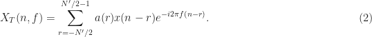


![\displaystyle S = \sum_r \left[ \sum_{n=N^\prime/2}^{N^\prime/2-1} a(n) x(r-n) e^{-i2\pi f_k (r-n)} \right] y^*(r) g(n-r) e^{-i2 \pi qr/N} \hfill (3)](https://s0.wp.com/latex.php?latex=%5Cdisplaystyle+S+%3D+%5Csum_r+%5Cleft%5B+%5Csum_%7Bn%3DN%5E%5Cprime%2F2%7D%5E%7BN%5E%5Cprime%2F2-1%7D+a%28n%29+x%28r-n%29+e%5E%7B-i2%5Cpi+f_k+%28r-n%29%7D+%5Cright%5D+y%5E%2A%28r%29+g%28n-r%29+e%5E%7B-i2+%5Cpi+qr%2FN%7D+%5Chfill+%283%29&bg=ffffff&fg=1a1a1a&s=0&c=20201002)

![\displaystyle = \sum_n a(n) e^{i2\pi f_k n} \left( \sum_r g(n-r) [x(r-n) y^*(r)] e^{-i2\pi (f_k + q/N)r} \right). \hfill (5)](https://s0.wp.com/latex.php?latex=%5Cdisplaystyle+%3D+%5Csum_n+a%28n%29+e%5E%7Bi2%5Cpi+f_k+n%7D+%5Cleft%28+%5Csum_r+g%28n-r%29+%5Bx%28r-n%29+y%5E%2A%28r%29%5D+e%5E%7B-i2%5Cpi+%28f_k+%2B+q%2FN%29r%7D+%5Cright%29.+%5Chfill+%285%29&bg=ffffff&fg=1a1a1a&s=0&c=20201002)
![\displaystyle S = \sum_n a(n) e^{i2\pi f_k n} \left( \sum_r g(n-r) [x(r-n)y^*(r)] e^{-i2\pi \alpha_0 r} \right). \hfill (6)](https://s0.wp.com/latex.php?latex=%5Cdisplaystyle+S+%3D+%5Csum_n+a%28n%29+e%5E%7Bi2%5Cpi+f_k+n%7D+%5Cleft%28+%5Csum_r+g%28n-r%29+%5Bx%28r-n%29y%5E%2A%28r%29%5D+e%5E%7B-i2%5Cpi+%5Calpha_0+r%7D+%5Cright%29.+%5Chfill+%286%29&bg=ffffff&fg=1a1a1a&s=0&c=20201002)


![\displaystyle S = \sum_n a(-n) e^{-i2\pi f_k n} \left( \sum_r g(-n-r) [x(r+n) y^*(r)] e^{-i2\pi \alpha_0 r} \right) \hfill (7)](https://s0.wp.com/latex.php?latex=%5Cdisplaystyle+S+%3D+%5Csum_n+a%28-n%29+e%5E%7B-i2%5Cpi+f_k+n%7D+%5Cleft%28+%5Csum_r+g%28-n-r%29+%5Bx%28r%2Bn%29+y%5E%2A%28r%29%5D+e%5E%7B-i2%5Cpi+%5Calpha_0+r%7D+%5Cright%29+%5Chfill+%287%29&bg=ffffff&fg=1a1a1a&s=0&c=20201002)
![\displaystyle = \sum_n a(-n) e^{-i2\pi f_k n} \left( \sum_r g(-n-r+n/2) [x(r+n/2)y^*(r-n/2)] e^{-i2\pi \alpha_0 (r-n/2)} \right). \hfill (8)](https://s0.wp.com/latex.php?latex=%5Cdisplaystyle+%3D+%5Csum_n+a%28-n%29+e%5E%7B-i2%5Cpi+f_k+n%7D+%5Cleft%28+%5Csum_r+g%28-n-r%2Bn%2F2%29+%5Bx%28r%2Bn%2F2%29y%5E%2A%28r-n%2F2%29%5D+e%5E%7B-i2%5Cpi+%5Calpha_0+%28r-n%2F2%29%7D+%5Cright%29.+%5Chfill+%288%29&bg=ffffff&fg=1a1a1a&s=0&c=20201002)


![\rho = C_x^\alpha(f) = \displaystyle\frac{S_x^\alpha(f)}{[S_x^0(f+\alpha/2)S_x^0(f-\alpha/2)]^{1/2}}, \hfill (11)](https://s0.wp.com/latex.php?latex=%5Crho+%3D+C_x%5E%5Calpha%28f%29+%3D+%5Cdisplaystyle%5Cfrac%7BS_x%5E%5Calpha%28f%29%7D%7B%5BS_x%5E0%28f%2B%5Calpha%2F2%29S_x%5E0%28f-%5Calpha%2F2%29%5D%5E%7B1%2F2%7D%7D%2C+%5Chfill+%2811%29&bg=ffffff&fg=1a1a1a&s=0&c=20201002)
![C_{x^*}^\alpha(f) = \displaystyle\frac{S_{x^*}^\alpha(f)}{[S_x^0(f+\alpha/2)S_x^0(\alpha/2-f)]^{1/2}}. \hfill (12)](https://s0.wp.com/latex.php?latex=C_%7Bx%5E%2A%7D%5E%5Calpha%28f%29+%3D+%5Cdisplaystyle%5Cfrac%7BS_%7Bx%5E%2A%7D%5E%5Calpha%28f%29%7D%7B%5BS_x%5E0%28f%2B%5Calpha%2F2%29S_x%5E0%28%5Calpha%2F2-f%29%5D%5E%7B1%2F2%7D%7D.+%5Chfill+%2812%29&bg=ffffff&fg=1a1a1a&s=0&c=20201002)


From what I understand the FAM and SCCA algorithm generates a tilted bifrequency plane, that being the value of alpha=0 lie across the primary diagonal of the matrix output, and there is only a single value for alpha = +/- Fs. This makes some sense, due to the fact that at least in the FAM I am conjugate multiplying each frequency bin column against all the other columns. Does that sound correct? Is there a proper technique for correcting this shift, so alpha=0 lies upon the x-axis? Would that cause points to lie upon Fs/(2*N) frequency spacing?
In a related question, when computing the spectral coherence (SOF), I can take the value of the SCF at alpha=0 which is essentially a PSD. I can take that and do circular shifts conjugate multiplies to get NxN matrix. In theory I can use that matrix to be the denominator in the SOF calculation, but since the FAM outputs in that diagonal fashion, how would I deal with that?
Also, is it a true statement that the SOF magnitude will always be 1 when alpha=0? Is the SCF or SOF magnitude always symmetric about the alpha=0 axis?
The difficulty here is that we must agree what “the matrix output” means to proceed. We can agree right now, however, that the SSCA proceeds strip-by-strip. Each strip FFT is the FFT of the product of the original complex-valued signal with one of the channelizer outputs. Each of these strip FFTs will contain a contribution to the PSD (alpha = 0). And each of the strip FFTs will contain N points, each of which corresponds to N different values of cycle frequency. So, I don’t agree with “there is only a single value for alpha = +/- Fs.”
What I do is create a table of SCF values as the SSCA proceeds with its strip FFTs. I end up with a data structure that has four elements: spectral frequency f, cycle frequency alpha, spectral correlation S, and coherence C. Then I can extract whatever “slices” I want from this structure.
Yes, you can use the SSCA-generated PSD values (those elements of the output that correspond to alpha = 0 in the non-conjugate SSCA output). However, there are only M of these values, one for each strip, and M << N, where N is the total number of samples processed (also the length of each strip FFT). So the spectral resolution of that effective PSD estimate is low (coarse) relative to the cycle resolution. This causes problems when the coherence quotient is formed, because the numerator and denominator have different resolutions. One way out of this is to form a stand-alone PSD estimate and use that for the denominator of the coherence. You can control the resolution of the stand-alone measurement.
I’m not sure about the FAM. I’ll need to look into it and do a FAM post!
Yes, the non-conjugate spectral coherence is always 1 for alpha=0, theoretically, provided that there is no point where the PSD is equal to zero. A good coherence estimator should always output very nearly 1 for this case. If it isn’t, you know you’ve got problems with your estimator, so definitely pay attention to this case.
You mean, is |S^(-a)(f)| = |S^(a)(f)|? Yes, for the non-conjugate SCF and coherence functions. But it is not true for the conjugate functions.
Thanks for the reply, I am new to this so still processing the concepts.
> And each of the strip FFTs will contain N points, each of which corresponds to N different values of cycle frequency. So, I don’t agree with “there is only a single value for alpha = +/- Fs.”
I am hung up on this concept. Once you do the strip FFTs, you get a resultant matrix which must then be mapped back into Sx in a particular way. Via this mapping, there appears to be only a single non-zero value at alpha=Fs, at F=0 and at alpha=-Fs, at f=0.
This mapping is mentioned in this reference http://www.dtic.mil/dtic/tr/fulltext/u2/a289815.pdf (24), and described in detail in section 3.3.3. It appears to essentially be a rotation mapping, where the region of support appears “diamond shaped” in the bifrequency plane. In the SSCA, the strips are diagonal slices. The highest alpha value in that region is alpha = Fs, which appears at f=0. Likewise at f=Fs/2 there is only a single value at alpha=0.
Does that make sense, or did I misinterpret things? I think each strip FFT does correspond to N different values of cycle frequency as you said, but each strip works at an offset of each other, so only one strip actually outputs alpha=-Fs, and the next strip outputs alpha=-Fs+1/Np/2, etc.
I think you are understanding just fine; I misinterpreted your earlier comment. Yes, that report by April has the diamond-shaped support region correct (this is independent of the SSCA of course), and you can see the diamond outline in the figures in my original post. I had forgotten about that report; thanks for reminding me aapocketz.
Hi there,
Thank you for the great informative posts related to this subject. I am a bit confused however regarding the frequency shifting of Sx by an amount of gamma=q*delta_alpha (see eq. 13 in aapocketz’ reference: http://www.dtic.mil/dtic/tr/fulltext/u2/a289815.pdf), such that the total frequency shifted expression can be evaluated using the FFT algorithm. Basically I just cannot mathematically figure out why multiplication of the TS cylic periodogram with exp[j*2*pi*gamma*m*Ts] relates to a shift in the value of alpha (one would expect an frequency shift such that Sx(n,f+gamma) ).
Thankfully your approach is the other way around, proofing that the SSCA provides us with an evaluation of the Fourier transform of the cyclic correlogram. What confuses me in your derivation though, it that in your third equation (where you substitute the complex demodulate X_T in spectral correlation function point estimate) you end up with an inner sum expression with iterative variable n. This variable is also used as the argument of the function S(n,f) and the window function g(n-r) (which is outside of the inner summation). Isn’t there something going wrong in the subsequent derivation due to this conflict in variable definition?
I hope you can help me,
Kind regards,
Vincent
I’m on vacation this week, but I will look into your question next week and provide a substantive reply. I may very well have made a math or notation error! Thanks for the careful read…
In the first paragraph of your comment, I believe you are talking about the complex-valued factor that we use in the TSM. I’ve previously tried to explain the origin of this factor in the TSM post. Can you take a look at that post and let me know if it doesn’t help? We can take it from there…
In the second paragraph, you point out an error in the SSCA development. Yes, there is a problem with the derivation, and some bad choices for notation! I will have to fix this. I don’t believe the basic conclusion will change, though. Thanks very much for pointing me to a flaw in the blog.
Hi Chad,
I’ve been following your blog recently and I really appreciate the detailed contents on cyclostationary. Currently I’m trying to recreate the simulation for SSCA, but I could not get converged coherently (not normalizing to 1).
I did try to use FSM method to estimate the PSD, but they seemingly on different scale altogether, although, with scaling that can be avoided. The result still looks that it didn’t normalizes properly.
With full FSM estimation, I can get it to normalizes properly.
Do you have any pointers on where I should look into?
Can you post a few more details about what is going wrong? It may be helpful to others to see what you are struggling with. You and I may need to take this to email to solve it, but for now, can you let us all know a little more?
We’ll get to the bottom of it eventually.
Thanks Chad for replying quickly.
Here is what I have right now.
Spectral correlation: https://db.tt/kZxefRuS
Spectral coherence: https://db.tt/PRBDKjVR
Those are generated using SSCA with FSM PSD.
I’ve also using the same waveform (your rect bpsk) to calculate using purely FSM method.
Spectral correlation: https://db.tt/VkPA90TU
Spectral coherence: https://db.tt/04Z0dxxb
Thanks, William
It’s hard to tell from the FSM plots, but it looks like the coherence (non-conj) for alpha = 0 is not unity across the band. This is the easiest thing to debug, perhaps, since we know that the coherence should be exactly one for every frequency. (You are just dividing the PSD by itself.) So if that is not coming out ‘1’, then you probably have an indexing error. Either that, or you are using two different PSD estimates, one for the numerator of the coherence, and one for the denominator, and they don’t match.
Here is the PSD comparison: https://db.tt/dsBEDztd
The blue represents FSM PSD estimate, the red dots represent SSCA alpha = 0 estimate
Something looks wrong with the FSM PSD in that plot. Can you send me the data files for both the red and blue dots?
Also, what were the parameters used in the FSM PSD estimate? (block length, width of smoothing window)
I forgot to close this topic thread and offer thanks to Chad for helping me out.
Looking forward to hearing more cs blog in the future.
Hi William S and Chad,
May I know how you managed to resolve your problem of the Coherence function not normalizing properly? I am having the same problem with magnitude scaling.
Currently, I am using matlab’s pwelch function to estimate the PSD, and then scaling the pwelch output to match the PSD estimate from SSCA at alpha=0.
I am sure this is incorrect, but this method of finding coherence using pwelch allows me to better detect spectral peaks much better than SSCA alone.
I have also tried estimating PSD using a frequency-smoothed periodogram, using a rectangular smoothing window of different lengths. However, I still obtain PSD estimates with a different scale from the SSCA.
This is the cyclic domain profile (maximum coherence across all alphas) of my test signal: http://imgur.com/gTUe8mY.
May I have some insights as to how I can solve this problem? Thank you!
Thanks for the comment Calvin. I also let William know you left it so he might reply as well.
I’m not sure if William had enough time to complete his coherence debugging to his satisfaction. Of course, my several implementations of the SSCA produce good coherences.
I think a possible strategy for you is to make sure that your various PSD estimates (SSCA, FSM, pwelch) have the correct shape and scaling independent of each other. That is, process a signal with an exactly known (analytically) PSD, such as white Gaussian noise with unit power (variance). Make sure each PSD is close to one across frequency. Then move on to other signals with known PSDs, such as PSK/QAM with IID symbols.
Also, the degree to which a spectral coherence estimate is accurate depends on the length of the processed data record and the spectral resolutions used in the SSCA and in the off-to-the-side PSD estimate, so there is some art to this task. Coherence can also go awry if the PSD contains discontinuities (e.g., step functions, impulses) or very rapidly fluctuating spectral regions.
What is the signal that you used to generate the estimates in your imgur link? I see that the maximum coherence for alpha=0 is about 2. Since the coherence for alpha=0 (non-conjugate) should be , you clearly have a factor-of-two difference between the psd-on-the-side estimate (denominator) and the SSCA output (numerator).
Thanks for the input Chad! You gave me a couple of ideas as to how to start debugging the coherence. One possible area I’ll look into is a power correction for pwelch and my PSD estimates. Once I get something working again I’ll update this thread.
As for my input signal, I’m using a srrc 16-QAM signal. Thanks for the help.
If you used a square-root raised-cosine 16-QAM signal with IID symbols to produce the cyclic domain profile shown in your imgur link above, we’ve got bigger problems than a PSD scaling factor. That signal has three non-conjugate cycle frequencies: ,
,  , and
, and  , and no conjugate cycle frequencies. Your plot shows at least
  significant cycle frequencies. Seems closer to a rectangular-pulse QAM pattern.
Hi Chad,
First, regarding my previous CDP plot:
You are right, I made a careless mistake in my signal generation. These are the corrected plots for a SRRC 16QAM signal. CDP: http://imgur.com/WetD7O9, Coherence: http://imgur.com/msOwflK.
Next, regarding the problem with normalising, it seems that the best coherence plots come from FSM PSD estimates that strongly mirrors the SSCA PSD (Sx at alpha=0). This means that a SSCA with coarser spectral resolution (i.e. smaller df) requires a corresponding FSM with a larger smoothing window. A FSM that is not sufficiently smoothed will produce spurious peaks in the coherence plot along the alpha=0 axis. These peaks are the cause of the larger than 1 magnitudes at alpha=0 on the CDP. A PSD that is not sufficiently smoothed will produce peaks.
Coherence: http://imgur.com/lwcp4vv
CDP: http://imgur.com/YrL65pM
Conversely, a PSD that is oversmoothed will cause dips below magnitude 1 along alpha=0 of the coherence plot. However, this does not affect the CDP plot.
Coherence: http://imgur.com/3KGP0u7
CDP: http://imgur.com/d1AUtuQ
My conclusion from all these is that the FSM PSD should mirror the SSCA PSD as closely as possible. This makes me question the need for a separate PSD estimate. Why should I be using a fine PSD estimate if ultimately I am smoothing it to match the SSCA PSD, which has a much lower spectral resolution. Would it not be easier just to interpolate the SSCA PSD to match spectral resolution (block length of alpha) and use that in my coherence calculations?
I would appreciate any help as I am quite puzzled by this seemingly contradictory situation. Thank you!
I view the interpolation of the SSCA-produced PSD values as a “separate PSD estimate.” That can definitely work. I would caution you to not make any solid conclusions, though, based on this one rather easy test case with a smooth underlying true PSD.
Chad,
Suggestion for improvement..I have been reading your blog to get a refresher and relearn, but there was an abrupt discontinuity in terms of Equation (1) above. I kind of had to look at other literature to see (if I am correct) your taking cross-correlation between two spectrograms. As a suggestion for improvement, is it possible to state the meaning of some of the variables of Equation (1), and how it came about? Why is there a positive q on S and then a negative q in the parenthesis? What is N? What is N prime?
Thanks
Masoud
I plead guilty to incompletely describing the SSCA! I did mention that a detailed examination of the method is in The Literature [R3]-[R5], and I hope it is clear that I did not author those papers nor did I have a hand in inventing/discovering the technique.
No, that is not correct. I wonder which literature you refer to (please leave citations if you reply to this comment). The SSCA produces a large set of point estimates for the spectral correlation function (SCF), which is described in detail in my SCF post. Spectral correlation refers (in the context of cyclostationary signal processing) not to the correlation of PSDs (“spectra”) or of spectrograms, but of two complex-valued time-series derived from downconverted narrowband components of a data-record or mathematical signal model of interest.
I think most of the variables are defined in the post, including the ones you mention such as and
and  . Which other variables are poorly defined? I added a few notes to the post to connect the time-in-seconds variables to the time-in-samples variables.
I don’t quite know how to answer this. “That’s just the way it comes out” is not very satisfying, I know, but it is all I have right now.
Hi Chad, in your FAM post there is a stride parameter L in equation (1) . Can this stride parameter also be used in the SSCA? What affect does changing the size of the stride parameter have on your estimates? I assume that the resolution of
  is unaffected by L because the cycle-frequency resolution is 1/N.
I’m a little unsure what the frequency axis represents when is non-zero. For
  the value at some frequency f represents the power contained in that frequency bin. But when
  is non-zero does the value at some frequency f correspond to the correlation between two spectral components that are located at
  and
and  ? I probably did a horrible job explaining my question but hopefully it made some sense.
Hi Christopher!
I edited your comment to include the dollar signs around the latex code you wrote. You need to do “DS latex e^x DS” instead of “latex e^x” in WordPress, where DS stands for the dollar sign $. If I type it the way I’m trying to communicate here, it will be typeset, and I can’t figure out how to use \verbatim in WordPress.
Yes, there is a stride parameter in the SSCA as well as in the FAM. See The Literature [R3], [R4] for lots of details. Too much striding will result in cycle leakage and false cycle frequencies in the SCF. I almost never use it in the SSCA. The primary purpose is so that you can reduce the storage for the channelizer values. But memory is plentiful, and so I avoid reconstructing the full-rate channelizer outputs from the strided (subsampled) ones by just storing them all for a stride of unity. Your mileage may vary.
Yes! At least for the non-conjugate SCF. For the conjugate SCF, the interpretation is that the SCF value at some f is the correlation between frequency components at frequencies and
and  . I strongly recommend you look at the full spectral correlation post, especially the material toward the end.
Thanks Chad! That clears up my questions. I did read your spectral correlation post which is very helpful. I was just struggling making the connection with the frequency axis but now I’m solid.
Hi Dr. Spooner,
I’m hoping this question will be of use to others. As you suggest, I am calculating the coherence by first taking an over-sampled PSD (in this case, N-points, to match the cycle frequency resolution), smoothing it using the frequency-smoothing method, and then finding the appropriate value for the relevant combination of f and alpha when doing the final mapping stage of the spectrum and strip FFTs to the bi-frequency plane. However, the coherence that I compute has some fairly large spikes that seem to coincide with the nulls in the PSD. I suspect that the PSD estimate and the SCF do not quite match up due to the different resolutions, and when the values of each are small, the division stage can cause some spuriously large coherence values just due to noise alone. I was wondering if you encounter this at all and how you mitigate it? Thanks!
Yes, I observe this effect as well. One thing to avoid is processing a noise-free signal using the coherence. The coherence quotient is not well-defined when one of the PSD values is zero. But the quotient can also be ill conditioned when the data contains features that are difficult or impossible to resolve, such as step-functions, impulses, and nulls. Spurious large coherence magnitudes can then result because the values in the denominator don’t properly reflect the variances of the two involved spectral components at (for the non-conjugate case).
To illustrate your question (and verify that I’ve understood it), here are some examples:
The noise I added to remove the large coherence values has one-tenth the power of the signal, so the main-lobe inband SNRs for the signals are still large (20 dB for the rect-pulse signal). The large coherence spikes for rectangular-pulse BPSK are due, as you suggest, to the nulls in the BPSK PSD occurring at ,
,  . The large coherence values for square-root raised-cosine BPSK are due to the frequency intervals outside of the signal band, which have theoretical value of zero, and in these measurements have a very small value.
Evidently, dividing by zero is a problem :-). So a mitigation strategy is to ensure that the denominator of the coherence does not ever get small. Recall that the coherence is given by
So you can add noise to your data prior to processing (ouch!), or you can artifically “inflate” the PSD that you use in your calculations by adding some small constant to it, for example.
Hi Chad,
I’ve implemented the SSCA, primarily using Eric April’s report mentioned and linked to in other comments above. The results generally match your plots in the FSM or TSM posts for the BPSK signal, so I believe I have it mostly correctly implemented.
My uncertainty is related to normalization and the effects of the window functions and
and  . When
  and
and  are simple rectangular windows, I get correct results, but the SCF levels vary by several dB when using other windows. I did ensure that the condition in April equation (12) was satisfied –
  . Oh, I did have to add a multiplication by
  , which I haven’t rigorously verified to be correct.
Based on my interpretation of April’s recommendations, I’ve mostly been trying to use Kaiser windows with for
for  and
and  for
for  .
.
I can use the exact same (with normalized energy) with my own implementation of Welch’s method for estimating the PSD, and it has no visible effect on the resulting PSD levels. Does this indicate an error in my SSCA implementation, as I suspect? Or what effect should I expect the windows to have on the SCF / SSCA?
Thanks for any clarification!
Good comment, Clint, and I appreciate it. I think I need to add another draft post to the (growing) list: Data Tapering in Spectral Correlation Estimators. For my benefit, yours, and that of all CSP Blog readers.
In the meantime … I looked up April’s report and the condition you mention is there, as it is in the Roberts/Brown/Loomis paper he cites (The Literature [R4]). But I don’t agree with it, and I don’t obey it in my SSCA implementations. In particular, the condition on is not obeyed by me, but the condition on
  is.
is.
The function is a genuine data-tapering window, and should be equal to one at its midpoint to preserve the level of the data it is shaping. The function
  is an averaging window. A good choice for
  is simply a rectangle with width
  and height
  .
.
I usually use a Chebyshev data-tapering window , but I can swap that out for MATLAB’s hamming.m or hanning.m or others and still get good results. All those windows have value of one at their midpoint and gracefully decay from there toward zero on either side, but they don’t have unit energy. If you do
x = hamming(64);
y = sum(x .^ 2);
z = sum(x);
you get y = 25.04 and z = 34.1.
The analytical approach to understanding the effects of and
and  is through representing all spectral correlation estimators as general quadratic transformations of the input data, which involves a two-dimensional kernel function. That function usually can be approximated as the product of functions relating to
  and
and  . See The Literature [R1].
I need to revisit all this carefully and attempt to explain it to us all!
Thanks so much, Chad!
The SCF levels output from my SSCA now seem to be independent of N and Np and the window functions, as they should be, and they match yours for the BPSK signal. I still have a normalization factor of 1/N that doesn’t match April’s report, but I’m assuming that isn’t a big deal – maybe a difference in the normalization of our FFT algorithms or an oversight or typo in his report, or I just can’t read again.
I’d love to see [R1] from your Literature page, but the asking price is around $3,000 online at the moment. I’ll see if I can get a copy through my library or something. 😉
Are you using an averaging window that has values of one or values of
  ? I use the latter, which implements a straightforward arithmetic mean (average value), but I do it by ignoring
  in the main algorithm, and then after the strip FFT, I just scale by
  . I do agree that the averaging window should have unit area. So maybe that’s your remaining factor.
I just verified that on amazon.com! Whoa! I mean, it is a good book, but not worth anywhere near that price. I wonder if people are actually paying that kind of money for the book. Perhaps I should sell mine!
So it turns out you were right – I was _effectively_ using a with values of
  . I was creating the correct
  , but it seems that the section of April’s report that I was using omitted the step where it was applied, and thus I neglected to apply it as well. That is, his equation (31) should also include a multiplication by the matrix
  .
.
Now I’m working on getting the conjugate version working – it doesn’t seem to be addressed directly in the references I’ve looked at so far, so now I’m trying to actually understand the equations I’ve implemented a little better to catch what the differences are…
Still working out a couple other issues with my SSCA for the conjugate SCF, but am I correct that the only difference is versus
  in equation (1)? I had been thinking that I would have to reverse some indices or something as in the conjugate cyclic periodogram, but that doesn’t seem to be the case with what I’ve been able to go through on the math thus far.
Of course, five minutes after I post my last comment, I discover a typo in my code, and now my conjugate SCF matches yours for the BPSK signal.
Glad to hear it!
Is the cycle frequency the same as the symbol rate or chip rate?
Thanks for the comment Bo!
For many digital signals, the symbol rate is in fact a non-conjugate cycle frequency. For direct-sequence spread-spectrum signals, the chip rate is typically a cycle frequency. But there can be many more cycle frequencies so, no, the cycle frequency set is not identical to the symbol rate. For many other signals, the dominant cycle frequencies can be related to other aspects of the modulation (for example, OFDM). In the post above, you’ll see an example of the blindly detected cycle frequencies for rectangular-pulse BPSK. That signal has many cycle frequencies, including harmonics of the bit rate.
Cyclostationarity of digital QAM and PSK
Cyclostationarity of DSSS
Gallery of spectral correlation
Gallery of cyclic correlation
Thanks!
I’m confused on the coherence part from the block diagram. Typically I think of coherence as the cross spectral density divided by the product of the auto spectral densities of the two inputs. In this case we’ve already taken the FFT. What am I missing?
Also which pairs are used for coherence calculation? All the channelized inputs go into the block diagram.
The spectral coherence function in CSP is indeed a cross spectral density divided by the (square root of the) product of the involved auto spectral densities. It is just that the cross spectral density involves two signals derived from one waveform. Have you looked at the spectral coherence post? You might appreciate The Literature [R150].
When applying a blind cycle-frequency estimator like the SSCA, I typically compute the coherence for each (f, alpha) pair for which the algorithm produces an estimate of the spectral correlation function. For N input samples and N’ strips or channels, that’s NN’ spectral correlation point estimates for the non-conjugate SCF and another NN’ for the conjugate. But if you have some cycle frequencies in mind, you can skip the SSCA (or FFT accumulation method), and just use the TSM or FSM to estimate the SCF, then use a side PSD estimate to compute the coherence for the known CF and various spectral frequencies f.
Hey Chad,
I’ve been working through implementing the SSCA using your blog and E. April’s report with good results. I’ve quickly come to respect the rather large computational costs. Another SCF estimate algorithm I’ve come across and implemented called the “Fast-SC” algorithm by J. Antoni looks to have some improved computational complexity and some other positive attributes in certain use cases. It’s published here: https://www.researchgate.net/publication/313389754_Fast_computation_of_the_spectral_correlation). After searching your blog and the literature page I didn’t see any references. Have you ever reviewed this estimation algorithm before? I would be curious to know your thoughts on it. The author also has some nicely documented MATLAB code to go along with the paper (https://www.mathworks.com/matlabcentral/fileexchange/60561-fast_sc-x-nw-alpha_max-fs-opt) which is rare!
Brad: Thanks much for stopping by the CSP Blog!
Yes, others have sent me that paper by Antoni. I have a post in the works. (Update December 2021: The post is published.)
For now, I’ll just say my preliminary conclusion is that the Antoni estimator can be faster than “FSM in a loop” or “TSM in a loop” for small ranges of cycle frequency. But it is still slower than a properly implemented SSCA, even without parallelization. That is, for the example in the code you linked to, Antoni looks at a range of cycle frequencies equal to![[0, 0.04]](https://s0.wp.com/latex.php?latex=%5B0%2C+0.04%5D&bg=ffffff&fg=1a1a1a&s=0&c=20201002) in normalized Hz, and when I run it (as is, using his signal but extended to
in normalized Hz, and when I run it (as is, using his signal but extended to  samples), that takes about 0.75 seconds (not including any of the plotting, just the function call). When I run my best C-based SSCA, I get the entire SCF and the entire coherence function, as well as coherence-based thresholding and cycle-frequency binning, reducing the entire calculation to the two (correct) detected cycle frequencies, it takes 0.4 seconds. A good MATLAB SSCA implementation I have does the same calculation, but it takes 1.6 seconds. So the C-based SSCA is faster, and it does a lot more than Antoni’s calculation, and the MATLAB-based SSCA is arguably faster in that it also does a lot more than look at that narrow set of cycle frequencies. When I put the FSM in a loop over Antoni’s restricted range of cycle frequencies, it takes 4.7 seconds, which includes the SCF estimate, the coherence estimate, and the maximization of the coherence magnitude over frequency.
So from those results, it looks like you can use Antoni’s method when you want to do FSM-in-a-loop style estimation for a small range of cycle frequencies, and you’ll get a benefit.
But if you increase the range of cycle frequencies in the Antoni code a bit, from![[0, 0.04]](https://s0.wp.com/latex.php?latex=%5B0%2C+0.04%5D&bg=ffffff&fg=1a1a1a&s=0&c=20201002) to
to ![[0, 0.2]](https://s0.wp.com/latex.php?latex=%5B0%2C+0.2%5D&bg=ffffff&fg=1a1a1a&s=0&c=20201002) , the code takes 27.5 seconds, whereas my FSM-in-a-loop takes 21.8 seconds. Antoni suggests modifying the Nw parameter. So I guess you have to choose the right Nw parameter for each combination of data length and cycle-frequency range. The SSCA execution times are unchanged, of course.
, the code takes 27.5 seconds, whereas my FSM-in-a-loop takes 21.8 seconds. Antoni suggests modifying the Nw parameter. So I guess you have to choose the right Nw parameter for each combination of data length and cycle-frequency range. The SSCA execution times are unchanged, of course.
I will have some comments on the paper too, and I’m not sure what exactly is being computed in the code. For example, the maximum allowable cycle frequency is rather than
  . This can happen when one does direct computation of the cyclic autocorrelation, for example, because the sine wave that you need to multiply the lag product by cannot be unambiguously represented for
  , but frequency-domain methods (and I thought Antoni’s was a frequency-domain method) don’t suffer from this problem. The nominal range of cycle frequency is
 ![[-f_s, f_s]](https://s0.wp.com/latex.php?latex=%5B-f_s%2C+f_s%5D&bg=ffffff&fg=1a1a1a&s=0&c=20201002) and the range for spectral frequency is
and the range for spectral frequency is ![[-f_s/2, f_s/2]](https://s0.wp.com/latex.php?latex=%5B-f_s%2F2%2C+f_s%2F2%5D&bg=ffffff&fg=1a1a1a&s=0&c=20201002) . The input data is real-valued, and the input cycle frequency range cannot contain negative cycle frequencies, which are both big problems for normal complex-envelope processing, in which the conjugate cycle frequencies are often negative (e.g., if the carrier frequency offset is negative, the doubled-carrier conjugate cycle frequency will be negative).
. The input data is real-valued, and the input cycle frequency range cannot contain negative cycle frequencies, which are both big problems for normal complex-envelope processing, in which the conjugate cycle frequencies are often negative (e.g., if the carrier frequency offset is negative, the doubled-carrier conjugate cycle frequency will be negative).
Good evening Chad. Did you complete the post on Antoni’s work you allude to in this comment?
Thanks,
John
Yes, I published a detailed post on it in October.
Hi Dr. Spooner,
I am just starting to learn about this subject matter before I attempt to write some code for probably either the FAM or SSCA method. My initial question is a high level one and may seem pretty basic (and will likely reveal my ignorance).
In my application the signal to be processed is fed from a single channel of an already existing polyphase channelizer. The selected channel output signal is thus already bandpass filtered (and as well is complex and basebanded). Given that, when looking at Fig. 6 of the Roberts-Brown-Loomis paper, or Fig. 1 of you SSCA blog, I see the system input being passed through bandpass filters. I don’t think I need those. Yes? No?
Thanks,
Brian
Welcome to the CSP Blog Brian! And to the field.
Yes, you do need those bandpass filters in the SSCA, which I denote in Figure 1 by the generic term “channelizer,” which as you know is just a bank of filters.
The provenance of your data to be processed doesn’t matter to the SSCA or FAM algorithms. The front-end channelizer in the SSCA determines the spectral resolution of the spectral correlation measurement, which is not dependent on the way that the input data is obtained. In other words, when we do spectral correlation analysis on some sampled data, the various ways that the original RF energy is processed (frequency conversions, filtering, level shifting, etc.) to eventually obtain a sequence of complex values corresponding to a sampling rate of Hz does not matter.
Perhaps your channelizer produces channels with width 1 MHz, perhaps only 10 kHz, I don’t know. But the bottom line is that you apparently wish to process the complex samples corresponding to one of those channels. Suppose the width is 1 MHz. Then maybe the channel contains some signals with width 200 kHz, or maybe the channels contain only portions of a 5-MHz-wide signal. The starting point for spectral correlation analysis is the same: apply a bank of bandpass filters to the incoming data.
The width of those front-end channelizer filters in the SSCA determines the spectral resolution of the measurement, which is intimately related to the quality of the measurement through the resolution product.
So your choice of channelizer parameters in your data-acquisition system is driven by your application, and the choice of the channelizer parameters in the SSCA is driven by your computational complexity constraints and your desired estimator-output quality. The number of channels in the channelizer and the length of the processed data block determine the computational cost.
I recommend reading up on the resolution product and the three resolutions in CSP.
Have I answered your question or did I misinterpret?
No misinterpretation. FYI, my polyphase channelizer has a 2x OS architecture with a signal BW per channel 0f 1.8 MHz (fsamp = 3.6 MHz).
Your answer is understood, thanks much.
I am now getting good results for BPSK signals. Can easily see carrier frequency and chip duration at distinct alpha values. Results not so good for QPSK or QAM. Is it possible to upload plots?
Brian’s plot added by The Management:
Do you mean “doubled carrier frequency” instead of “carrier frequency”?
The reason you cannot get an estimate of the doubled carrier frequency with accuracy on the order of the cycle-frequency resolution (reciprocal of the processed-block length) is that the QPSK and 4QAM signals do not possess conjugate cyclostationarity. That is, their second-order cumulants for or
or  are identically zero. Equivalently, the conjugate spectral correlation function is identically zero (the surface of the theoretical function is zero-valued). So you see the nice spikes at twice the carrier (8.2 MHz) for BPSK, but just kind of a blob for QPSK and 4QAM. Another way of saying this is that for QPSK and 4QAM (and all the other PSK and QAM signals with constellations that have more than two points and a two-fold symmetry in the real/imag plane) there are no second-order cycle frequencies relating to the carrier.
However, many of these signals have non-zero cyclic cumulants for , and since the general formula for their cycle frequencies is
  , you can get an estimate of
  with accuracy about equal to the cycle-frequency resolution. But then you have to do quartic nonlinear processing to the signal instead of just quadratic, like for BPSK, so there is a noise penalty.
Simple suggestion: Try squaring your signal first, then apply what you’re already doing. You’ll need to watch out for aliasing if the carrier frequency offset is a significant fraction of the sampling rate.
Before I go on to study higher order cyclo, I should mention that indeed squaring the signal enables SCCA to produce nice spectral lines at 4fc for QPSK and MQAM (at least up to a 64 point square constellation).
Interestingly 8PSK did not work so well, but when I square the signal yet again, I get a nice spectral line at 8fc.
Thanks Dr. S.
You’re quite welcome!
Yes, you need at least an eighth-order nonlinearity to force each 8PSK constellation point to map to a single constellation point, which then leads to a constant component in the complex envelope (perfectly downconverted) signal, or to an additive sine-wave component with frequency in an imperfectly downconverted signal (here
  is the carrier frequency offset). This works but really suffers when there is significant noise present in the signal band.
You can predict the minimum required order of nonlinearity by looking at the tables of moments and cumulants in the PSK/QAM post.
Hi Chad.
I think I’m missing something. You state above, “The demodulates are formed by short-duration (N’) FFTs,” where N’ is also the number of channels. Similarly, R4 in The Literature states, “a(r) is a data tapering window of length T=N’Ts seconds. For convenience, the quantity $\delta a$ is defined to be the bandwidth of the input filters; hence for this system the bandwidth of the input filters is also the frequency resolution of the estimate…”
It seems like N’ defines two things: the frequency resolution of each channelizer FFT, and the number of channels). I don’t understand why (or if) they need to be the same.
The kids are back in school, hence I am sleep deprived. Please forgive me if I’m missing something obvious.
So the way I look at it is that we define the number of channels–the number of data samples we Fourier transform in the sliding-FFT function at the beginning of the SSCA algorithm–and the tapering window , and the frequency resolution follows from those choices and the basic properties of the Fourier transform.
Agree?
“Agree?” I think so. I’ll try to summarize my understanding, then ask a pair of related questions.
The axis of the
  plane is divided into N’ points by our SSCA strips (channels). That’s the simplest way for me to visualize the relationship between N’ and frequency resolution, although I understand the shrinking region of SCF support for other values of
  . Additionally, R4 presents the concept of a diamond-shaped Cyclic Spectrum Analyzer (CSA) cell. The CSA cell covers the continuous area in the
  plane that contributes to a single point estimate. The axis of the CSA diamond aligned with the frequency axis has a width (in normalized units) of 1/N*, where N* is the number of samples passed by
  . So the SSCA frequency resolution is still set by N’, but you might as well match the width of the CSA cell (1/N*) with the frequency spanned by the SSCA strip (1/N’). Hence the statement quoted above from R4, beginning with “For convenience…” You also need to design
  to minimize its transfer function’s sidelobes to avoid cycle leakage, etc., etc.
Q1: When you say “sliding” FFT, do you mean there is overlap in the time domain samples (windowed by ) used to generate successive FFT outputs? The SCF implementation I took off our shelf does that.
Q2: R4 seemed to clearly indicate (though I don’t have the passage handy to quote) the channelizer is outputting frequency domain samples that are then point-by-point multiplied with the time domain data that generated them. Heaven forbid I doubt Bill Brown, but that feels so counterintuitive that I can’t help baulking. Am I understanding R4 correctly?
PS: I’m rusty on LaTeX, let alone its use in WordPress. If my response looks like garbage, I’d appreciate a little clean up by The Management.
Thanks for using latex! You don’t need the ” ” around the latex format strings. Also, make sure there isn’t a space between the first dollar sign and the keyword latex. I fixed the latex format strings in the comment.
Yes. The parameter is typically called in the SSCA descriptions. It sets the amount of overlap between successive
  data subblocks that are to be tapered and DFT’d. I typically use
  , meaning that we slide over by a single sample to obtain the next subblock. The motivation for larger
  , which means less overlap than for
  , is to save memory. Larger
  means you’re effectively subsampling the channelizer outputs. But memory isn’t a big deal, and you have to ensure that the channel sequences are back up to the input-data rate before multiplying them by the input data anyway, so
  avoids the required interpolation step when
  .
.
This is an important concept to bring up. Clearly we say that the FFT produces a set of ‘frequency-domain points’ for an
  -sample time-domain input. But here we are applying the FFT to a sequence of data blocks, so we obtain a sequence of ‘frequency-domain vectors.’ Just focus on one of the FFT bins. We can associate the sequence of FFT values for that bin with a time index–the start time of the block (or the middle time, or end time, or whatever). So now we have a time-domain signal, produced by a sequence of frequency-domain operations (the FFTs). That is, the action of the channelizer step in the SSCA is to produce
  individual temporal sequences. If
  , then these temporal sequences are sampled at the same rate as the input signal. So we can interpret the multiplication of one of the channelizer output sequences by the input data as the multiplication of two time-domain signals.
It is like how we might speak about the output of a bandpass filter. On the one hand, we can interpret the BPF as multiplying the Fourier transform of the input by the Fourier transform of the impulse-response function and then inverse transforming–lots of frequency-domain ideas. On the other hand, the output of the BPF is also exactly equal to the convolution of the impulse-response function with the time-domain signal–zero frequency-domain ideas.
The channelizer here is just a (relatively crappy) bank of bandpass filters.
You buying what I’m selling here?
Hold the phone. Am I understanding correctly that each channel out of the channelizer is just one of the FFT bins? I.e., is the procedure: samples using the window defined by
  ;
; );
); and repeat steps 1-3 until
  samples have been generated for the longer strip FFTs?
1. Select
2. Take the FFT of those samples;
3. Multiply each bin by the reference sample (e.g. sample
4. Increment by 1 the samples windowed by
If the above is correct, is it the same approach analyzed by R4? In particular, I’d like to verify their estimates of computational complexity are applicable.
Yes, I think your 4-step description is consistent with the SSCA point-estimate formula.
However, let me try to clarify, although perhaps I will be perceived as pedantic.
The samples you transform with the -point channelizer FFT are not defined by the taper
  . They are merely defined by sliding along with time (sample index) and picking up the next
  points. You then apply the taper to those points.
I believe this is correct. However, it is typically more efficient and perhaps easier to code if you do all of the channelizer FFTs first. Then you take each channelizer sequence (corresponding to one of the FFT bin indices over time [samples]) and multiply by the original input data. Then take the
  -point FFT.
Yes. You can see my complexity analysis here.
This has been so hard for me to wrap my head around.
The conclusion I’ve come to is that takes in a time-domain signal and outputs a time-domain signal, just as if it was using a non-FFT-based channelizer (mixer+lpf), but with greater computational efficiency.
This is accomplished by not summing for each , like we would for in a traditional FFT use-case.
I think the notation to describe this process is where the confusion boiled down to.
I finally understand it now, though.
Once again. Thank you.
What do you mean by ‘not summing for each f?’
Eq (2) is:
If you fix and
and  , you just have the finite-time Fourier transform of the signal
 . If you consider a collection of
  , with fixed
  , you’ve got a time-series
 for
for that are in the collection.
(signal) that corresponds to the complex-valued Fourier transform at frequency
the instants of time
If you consider a collection of and also a collection of
  , then you
 corresponding to your
 .
.
have a vector of Fourier transform values for each
collection of frequencies
If you let the collection of frequencies lie on a regular grid and their
 , then you can perform the calculation for each
  using
using
number is
the fast Fourier transform.
When slides along in time, and we use
  frequencies
  , then
  represents the output of an FFT filterbank. See also My Papers [31].
Excellent. I got 90 minutes of sleep last night, so spelling things out is much appreciated.
I got the SSCA working and figured I should qualify the outline I made above by mentioning a step I initially overlooked. Equation 2 in R4, for calculating the demodulates, differs from the definition of the FFT (e.g. in scipy, or Matlab) in the relationship between the limits of integration and the time shift of the input and the FFT’s complex exponential. Massaging the math in Eq. 2 made the necessary reference sample and other tweaks apparent.
Glad to hear you’ve got the SSCA working, and thanks for closing the loop with this comment John.
The discrepancy between the limits of the sum in typical software-package FFT calls and the limits in the continuous-time sliding FFTs in CSP is a continual pain. I’ve pointed it out for the TSM and FAM, and of course it applies here too. Really appreciate your confirmation and comment, which helps CSP Blog readers for sure.
Hello dr.Spooner,
nice post. I just want to ask if I properly understand how to set detla N to achieve good resolution in frequency so if I set N from 8 to 128 with sampling frequency 2k. That means I have resolution in time from 0.0004 to 0.064 or in frequency from 15.6 to 2500 ? I think I understand how to set delta alpha ( if I want to achieve resolution in Baud rate I set alpha from 0.005 to 0.5 with 0.005 step when I apply Fs.*alpha in final CAF figure). I have also code in Matlab. Thank you for your response. Have a nice day.
My code:
clc;
clear all
close all
%%%%%%%%%%%%
M = 2;
Fc = 200;
Fs = Fc*10;
n_bit = 2000;
Fb = 50;
Td = n_bit/Fb; % Time duration, sec
spb = Fs/Fb;
fSpan = 2;
N_psd = 1024;
%%%%%%%%%%%%
data = randi([0 M-1],n_bit,1);
dmodData = (pskmod(data,M));
dmodData = awgn(dmodData,3,’measured’);
txFilter = comm.RaisedCosineTransmitFilter(“Shape”,”Square root”,”RolloffFactor”,0.3,”FilterSpanInSymbols”,fSpan,”OutputSamplesPerSymbol”,spb);
txfilterOut = txFilter(dmodData)’;
time = 0:1/Fs:Td-1/Fs; %
freq = 0:1/(Td-1/Fs):Fs; %
% figure(420)
% plot(time,txfilterOut)
carrier = exp(1j*2*pi*Fc.*time); %
txfilterOut = txfilterOut.*carrier; %
% figure(1)
% plot(time,real(txfilterOut),’r’)
% hold on
% plot(time,imag(txfilterOut),’b’)
% title(‘time domain’)
spek = (abs(fft(txfilterOut)));
% figure(4)
% plot(freq,spek)
% title(‘freq. domain’)
num_blocks = floor(length(txfilterOut) / N_psd);
S = txfilterOut(1, 1:(N_psd*num_blocks));
S = reshape(S, N_psd, num_blocks);
I = fft(S);
I = I .* conj(I);
I = sum(I.’);
I = fftshift(I);
I = I /(num_blocks * N_psd);
freq_c = linspace(-Fs/2,Fs/2,N_psd); %[0:(N_psd-1)]/N_psd – Fs/2;
% figure(666)
% plot(freq_c,10*log10(I))
% title(‘PSD’)
carrier = exp(-1j*2*pi*Fc.*time); %
txfilterOut = txfilterOut.*carrier; %
spek = (abs(fft(txfilterOut)));
% figure(3)
% plot(freq,spek)
% title(‘demo’)
%%%%%%%%%%%%%%%%%%%%%%%%%%%%%%%%%%%%%%%%%%%%%%%%%%
alpha = 0.005:0.005:0.5; %Resolution in Baud rate 10 (from 10 to Fs/2) %%%%%%%%%%%%%%%%%%%%%%%%
deltN = 128:32:256; %Resolution in Baud rate 10 (from 10 to Fs/2)
CAFko = zeros(1,length(alpha));
for i = 1:length(alpha)
for j = 1:length(deltN)
num_blocks = floor(length(txfilterOut) / deltN(j));
txfilterOutte = txfilterOut(1, 1:(deltN(j)*num_blocks));
modulplu = txfilterOutte.*exp(1j*2*pi*(Fc+alpha(1,i))/2.*[1:(deltN(j)*num_blocks)]); %
modulminu = txfilterOutte.*exp(1j*2*pi*(Fc-alpha(1,i))/2.*[1:(deltN(j)*num_blocks)]); %
modulplu = reshape(modulplu, deltN(j), num_blocks);
modulminu= reshape(modulminu, deltN(j), num_blocks);
x1 = fft(modulplu);
x2 = fft(modulminu);
I = x1 .* conj(x2);
Isum = sum(I.’);
Isum = fftshift(Isum);
Iabsft = Isum /(num_blocks * deltN(j));
CAFko(1,i) = CAFko(1,i) + sum(abs(fftshift(ifft(Iabsft))));
end
end
alpha = Fs.*alpha;
figure(2)
stem(alpha,CAFko)
title(‘SSCA CAF’)
I’m not sure what you are trying to do here. Are you trying to implement the SSCA?
Also I don’t recall using ‘delta N’ in the post (your ‘detla N’). You don’t want to use such small values for N, the total number of processed samples, in any CSP algorithm.
To implement the SSCA, you need to channelize your data (apply a sliding FFT with length N’ and retain the resulting N’ complex-valued signals each with length N), then multiply each of those channels by the input signal data, and finally Fourier transform (N points) each of those N’ vectors.
Sorry I didnt understand how deep the problem is. So please I have a few questions which came in way how to perform mentioned channelizer. The steps to obtain channelized data if I understanded right is:
1. get N’ points from x(t) so N is x(0) to x(N-1)
2. repeat the process with incremented position in x(t) by 1
3. get signal with length N from steps 1 and 2
4. multiply signal from 3rd step with input signal x(t)
5. fft the result from 5th step
This is how I understanded it from your comment.
When I search for some info in web Im searching for fft filter bank but I dont see any connection with sliding FFT. When I search for sliding FFT I get info about sliding DFT and the Goertzel algorithm. Sorry for poor knowledge in channelizer problematics but Im trying to do my best. Thank you for your answer and patience.
The channelizer in the SSCA is the implementation of equation (2), where is discrete time and
  is discrete frequency. In terms of your steps above, the channelizer is steps 1-3 with the addition that each obtained block of
  points of
  are Fourier transformed. Then your steps 4 and 5 go on to implement the remaining portions of the SSCA algorithm.
I found solution in commP25ssca.m which is function in Matlab. Now I think I can implement channelizer but after that they use in SSCA step which is called replication and multiplication. After that they just compute SCF. I saw your post on this function and Im trying to understand it. I set L = 1, but I have stuggle with delta_alpha and delta_f. In your post you set the parameters delta_alpha = 1/65536 and delta_f = 0.0625 with sampling frequency 1. I have no clue how to properly set those parameters with sampling frequency not equal to one like in your example.
btw: sorry for posting code like this but is there any other way how to show you my progress?
My code:
clc;
clear all
close all
%%%%%%%%%%%%
M = 2;
Fc = 200;
Fs = Fc*10;
n_bit = 1000;
Fb = 200;
Td = n_bit/Fb; % Time duration, sec
spb = Fs/Fb;
fSpan = 2;
N_psd = 1024;
%%%%%%%%%%%%
data = randi([0 M-1],n_bit,1);
dmodData = (pskmod(data,M));
txFilter = comm.RaisedCosineTransmitFilter(“Shape”,”Square root”,”RolloffFactor”,0.3,”FilterSpanInSymbols”,fSpan,”OutputSamplesPerSymbol”,spb);
txfilterOut = txFilter(dmodData)’;
time = 0:1/Fs:Td-1/Fs;
freq = 0:1/(Td-1/Fs):Fs;
%%%%%%%%%%%%
carrier = exp(1j*2*pi*Fc.*time);
xx = txfilterOut.*carrier;
fs = Fs;
dalpha = fs/65536;
df = fs/16;
N = fs/dalpha;
Np = fs/df;
disp(‘observation time T in discrete domain ‘ + string(fs/N) + ‘ seconds’)
disp(‘window time Tw in discrete domain ‘ + string((fs/Np)) + ‘ seconds’)
L = 1;
Npl = N/L;
NN = (Npl)*L+Np;
if length(xx)<NN
xx(NN) = 0;
else
xx = xx(1:NN);
end
x = zeros(Np,Npl);
for k = 0:Npl-1
x(:,k+1) = xx(k*L+1:k*L+Np);
end
a = hamming(Np);
XWin = a.*x;
XFFT = fftshift(fft(XWin));
X = [XFFT(:,Npl/2+1:Npl) XFFT(:,1:Npl/2)]; %-N/2 N/2
E = zeros(Np,Npl);
for idxl = -Np/2:Np/2-1 % length of l is Np
for k = 0:Npl-1 % length of k is P
E(idxl+Np/2+1,k+1) = exp(-1i*2*pi*k*L*idxl/Np);
end
end
XT = X.*E;
XRep = zeros(Np,Npl*L);
for k = 1:Npl
XRep(:,(k-1)*L+1:k*L) = XT(:,k)*ones(1,L);
end
% Multiplication
% Convert input vector into a matrix, the vector first becomes a row
% vector, and repeat Np times. xc is (Np,N), the same size as XR
inputRep = xx(1:Np)';
XMul = conj((XRep.*inputRep)');
% Centered N-point FFT (zero frequency in the 0 bin)
XFFT2 = fftshift(fft(XMul));
XFFT2 = [XFFT2(:,Np/2+1:Np) XFFT2(:,1:Np/2)]; % Output of Figure 5
M = abs(XFFT2);
% Convert M to Sx
Sx = zeros(Np+1,2*N+1);
for k1 = 1:N
k2 = 1:Np;
alpha = (k1-1)/N + (k2-1)/Np – 1;
f = ((k2-1)/Np – (k1-1)/N) / 2;
k = 1 + Np*(f+0.5);
n = 1 + N*(alpha+1);
for k2 = 1:Np
Sx(round(k(k2)),round(n(k2))) = M(k1,k2);
end
end
alphao = (-1:1/N:1)*fs; % cyclic frequency (alpha)
fo = (-0.5:1/Np:0.5)*fs; % spectral frequency (f)
figure(1)
surf(alphao,fo,Sx)
shading flat
xlabel('alpha');
ylabel('f');
zlabel('Sx');
You could use imgur to post plots?
The parameters that you can control in CSP algorithms are things like the number of processed samples and the length of a channelizer (SSCA) or FFT (TSM)
  . Those choices determine the cycle-frequency resolution, the temporal resolution, and the spectral resolution. They also determine the computational cost.
The cycle-frequency resolution is , the spectral resolution is
  , and the temporal resolution is
  . You want to always pick
  and
and  so that the resolution product is large (
 ).
).
Moreover, you want to pick large enough that you can process a sufficient number of the involved random variables (bits or symbols, say).
Before you can really get good at writing the code and, especially, using it, you have to understand the basics of the underlying estimator concepts. So look at the posts linked to in this reply and see if that helps.
Hello Dr. Spooner,
I’m trying to undertand the channelizer step of SSCA. I used your BPSK signal code without noise stored in x_of_t value. If I understood it correctly I shoud have in my channelizer XT value from eq.2 . I’ve read some articles in whitch is written about mentioned sliding FFT (https://ccrma.stanford.edu/~jos/sasp/DFT_Filter_Bank_I.html and also https://www.comm.utoronto.ca/~dimitris/ece431/slidingdft.pdf). The sliding FFT is spectial type of STFT with rectangular window (tapper) which I have already implemented in my code. The question is for to increment f in XT(n,f) from eq.2.
As I said I used your x_of_t variable so I rather dont post all your bpsk code here.
If you be so kind and please look at my part of code:
nframes = 16;
N = 4086;
ReferenceSample = fft(x_of_t(1:N));
window = rectwin(N)’; %rectwin in sliding FFT
for i=1:nframes
k = [i:i+N-1];
tapper = window.*x_of_t(k);
bin = fft(tapper);
channelizer(i,:) = bin.*ReferenceSample;
end
Thank you
I see I forgot to reply to this comment Miropele. Sorry about that. Are you still interested in an answer, or have you moved on?
I want to apologize about previous comment. I spotted numeroud elementar mistakes after posting the comment. My code shoud look like this not like in the previous comment.
My code:
nframes = 8;
N = 4096;
ReferenceSample = fft(x_of_t(1:N));
window = rectwin(N)’; %rectwin in sliding FFT
for i=1:nframes
k = [i:i+N-1];
tapper = window.*x_of_t(k);
bin(i,:) = fftshift(fft(tapper));
end
alpha = linspace(0,1/2,nframes);
for i=1:nframes
k = [i:i+N-1];
E(i,:) = conj(exp(1j*2*pi*(1-alpha(1,i))/2*k/N));
end
XT = bin.*E;
frek = linspace(-1/2,1/2,N);
alf = alpha’;
[efko,alk] = meshgrid(frek,alf);
figure(1)
surf(alk,efko,10*log10(abs(bin)))
This is the question you posed in the previous comment. I assume it is the question here, since there is no new question.
Unfortunately, I don’t understand the question due to grammar and it might be incomplete (?).
Are you trying to visualize the output of the channelizer in the SSCA?
If the data-tapering window is a rectangle, you do not need to actually do the taper multiplication. If the taper is a unit-height rectangle, you can just ignore it completely. If it is a rectangle with non-unit height, you can account for it later in the processing, by scaling.
Sorry I’m trying to do my best.
Yes, I’m trying to visualize the output of the channelizer for verification of success in this particular point (to obtain channelized data). So if I obtain bin(i,:) = fftshift(fft(tapper)); where tapper is just x(t) data with length N (e.g. N=4096) shifted by L=1 mutiple times, for example let say 16. I got (XT from eq.2)16×4096 mattrix am I right ?
What you want to do is choose a much smaller size for the channelizer width. Say, 64 instead of 4096. Then if you have a data record that is, say, 32768 samples long, your channelizer matrix would be 64×32768 (neglecting any edge effects as the 64-pt channelizer window slides off the end of the data vector). Each row would be the output of one of the channels.
Thank you for your bottomless patiencie with me.
I finally understand how to perform these first steps of SSCA. I particulary undertood it by this comment and via the FFT accumulaction article where is graphicaly demonstrated know-how of channelizer to point where I get tappered and transofrmed data to frequency domain.
But the struggle for me have not ended jet.
I understand it until third step from FFT accumulaction estimator article to point when I need to provide phase shift to obtain XT. Same method is graphically described in next picture from Da Costa paper.
https://imgur.com/a/cUHElcO
I have done it by this piece of code (btw: Np = 64 … and P is basically N (if L ==1)):
% Phase shifting
E = zeros(Np,P);
for idxl = -Np/2:Np/2-1 % length of l is Np
for k = 0:P-1 % length of k is P
E(idxl+Np/2+1,k+1) = exp(-1j*2*pi*k*idxl/Np);
end
end
XT = X.*E
where X is tappered data transformed to frequency domain. Then to obtain spectral correlation function (SCF) I need to multiply it with conjungate reference signal with length N (i.e. N = 32768) like in this picture ?
https://imgur.com/a/Fwqp5kk
so the final piece of code will be ??? :
for i = 1:Np
S = XT(i,:).*conj(x(1,1:N));
SCF(i,:) = fft(S);
end
Thank you again and have a nice day.
I can’t tell if you have shifted your focus to the FAM or are still trying to implement the SSCA.
Perhaps you should fully focus on the FAM, since the step-by-step instructions on the FAM post are more understandable?
Both the FAM and the SSCA have a hard step at the very end that involves assigning the correct pair to each point estimate.
Have you studied the comments on both posts? A lot of people have come before you…
In your post on the [TSM](https://cyclostationary.blog/2015/12/18/csp-estimators-the-time-smoothing-method/), you write “In practice, the FFT is used to create each cyclic periodogram, so their relative phases are no longer taken into account.”
I’m struggling a little to understand this, exactly.
There are two stages of FFTs in the SSCA. The quote above only applies to the first stage FFT, correct? Not the second stage? It’s exclusive to the polyphase filter bank architecture?
I don’t do explicit phase compensation in the SSCA. Only in the TSM and FAM. The FFT filterbank (“channelizer”) in the SSCA produces streams of data from the input data. Each of those is a narrowband component–time-series–of the input, and the only temporal effect to worry about is the overall delay imposed by the filterbank.
When we are explicitly averaging sets of FFTs arising from a temporally hopped blockwise kind of operation, like the TSM, we have to worry about the phase relationship between the complex FFT coefficients from block to block. If we just apply the FFT to each block, and then average them, it’s as if we have temporally shifted each data block to prior to every FFT application. And that isn’t consistent with the way the signal evolves over time.
Anyway, I’m a little confused because this comment is on the SSCA post, but references my statement from the TSM post.
My mindset is that I ultimately care about the SSCA, but want to make sure that the statement from the TSM wasn’t assumed in the SSCA. This helped me to understand. Thank you.
Hi Chad,
I am having a really hard time implementing the Coherence in SSCA. I was able to compute the SSCA producing the same pictures you have for SSCA using this code:
%% SSCA (Strip Spectral Correlation Analyzer)
N = 2^16;
x = y_of_t(1:N); x = x(:).’;
xc = conj(x); xc = xc(:).’; %conj(x)
Np = 2^6;
x = [zeros(1,Np/2),x(:).’,zeros(1,Np/2)];
% constant TPI = 2*pi*i //(Two-Pi-i)
TPI = 2*pi*1i;
% tapering window
a = chebwin(Np);
a = a(:)’;
% pulse function g = 1/N
g = 1/N;
% demodulates:
E = exp(-TPI*(1:Np)’*(-N/2:N/2-1)/Np);
Xt = zeros(Np,N);
for r = 1:N
Xt(:,r) = fftshift(fft( a.*x(r:r+Np-1)));
end
X = Xt.*E.*repmat(xc,Np,1)*g;
% SSCA:
S = zeros(Np,N);
for k = 1:Np
S(k,:) = (fft(X(k,:)));
end
Now I was thinking of how should I approach the problem of Coherence implementation and I came up with several options:
1. I have to use some approximation of the shifted PSD for the denominator to compute the coherence which will not be sampled precisesly as the output of SSCA. One can surely obtain how big the error is using this approximation which could then be used to get sufficiently good aproximation. This seems to be difficult, also one would then have to compute huge amount of shifted PDFs which seems to disolve all the advantage obtained using SSCA.
2. I could compute exact denominator value for each f-alpha pair of the plane. That means N*N’ FFTs, which seems to be a) dumb b) not within computational power of a common PC.
3. I could “sample” f-alpha plane and from that obtain indices k and q. But after some time I realized k and q are integers and for any general point of f-alpha plane I cannot guarantee that the indices k and q are integers.
So I am pretty desperate. I’d be very grateful for any suggestions for the Coherence. Also if you’d check the code I use to produce SSCA, it seems to work, but now I am pretty insecure.
Thanks for the blog. 🙂
Jakub
I was playing around a bit and I got to formula to compute shifted periodogram for a given ‘k’ and ‘q’ (i.e. SCF but without smoothing). Basically I looked at the formula for computing SCF and removed the smoothing (big ouch!). and
and  I pluged in the formulas
  and
and  . This led me to some matrices one for
  (of dim
  ) and other for
  (of dim
  ). I then summed up the dimension coinciding to time vector (somewhat fft for one f I guess – didnt use fft to implement this) and finally multiplied vectors element by element thus producing (of dim
  ) matrix whose elements (resp. its positions) should match the original SCF. I have code producing this:
Now for
S0_denom_plus = x*exp(-TPI*((1:Np)’-1-Np/2)/Np.*(0:N+Np-1)).’;
S0_denom_plus = S0_denom_plus(:);
S0_denom_minus = NaN(N,1);
blocks = 8;
for ix = 1:blocks
int = (1+round(N/blocks*(ix-1))):round(N/blocks*ix); int = int(:).’;
S0_denom_minus(int) = x*exp(-TPI*-((int)-1-N/2)/N.*(0:N+Np-1)’) ;
end
S0_denom_minus = S0_denom_minus(:).’;
S0_denom = S0_denom_plus.*S0_denom_minus;
COF = S./sqrt(S0_denom);
(Just a note to the blocks: Matlab had problem computing such a big matrix multiplication, so I chopped it into several blocks).
Now the thing is it produces something somewhat similar to the pictures you provided, but! it seems to have some flaws init. First when I plotted the COF for alphas close to zero it wasn’t normalized to one as it should be (it wasn’t even some any constant function). And second if I take say top 500 points there are some false points which coincise to smaller denominators values (smaller like hundreds of magnitude, which is smaller comapared to the rest of the denominator absolute values).
Now my question(s) is(are) did you ever try this approach? Do you think it is a trash? Could ommiting the smoothing result in the described behaviour? Did anyone come up with how one could do the coherence in the strips directly in SSCA (which is kinda what I was trying to do)?
Well, this got way larger than I originaly meant to, sorry for that.
Hope you have a nice week(end?). 🙂
Jakub
Yes, I have seen people try to form a matrix for the coherence denominator for the whole surface. You trade off, maybe, memory for speed compared to the loop-over- that I described in the previous reply. But that loop can itself be parallelized, and it isn’t particularly expensive in terms of computations.
In your code and formulas above, there are things I don’t understand, but that’s separate from the notion of trying to compute the entire denominator and then doing one big matrix divide. For example, I don’t know why and
and  have different dimensions. In the definitions of S0_denom_plus and S0_denom_minus, I see each one is not the periodogram, but
  multiplied by a complex exponential.
If the coherence for is not very close to one for all
  in the estimator, it isn’t worth checking the other parts of the surface until you get that part right. And that is my advice–keep trying with the coherence until you get the PSD coherence correct. Then, generally, other parts will be correct too (but not guaranteed of course).
I would be concerned with using the unsmoothed periodogram in place of the PSDs in the coherence formula–the periodogram is highly erratic. You will likely have lots of falsely large coherence values. Better to just do a simple side estimate of the PSD and loop over all the .
.
Jakub: Thanks so much for the comment and checking out the CSP Blog!
I looked at your code and ran it. It is pretty close to complete in terms of the SCF.
I do the SSCA in MATLAB just a little differently (I skip your E()), but I could make a couple small changes and get a valid PSD out of the SCF estimate:
In terms of your 1-3 above, you don’t need to work quite that hard to compute the coherence. You want the denominator PSDs to correspond to frequencies no more accurately than the native cycle-frequency resolution, and generally you don’t even need that.
Just create a reasonable PSD estimate using the TSM (try it with an FFT length of 512 and use all your data). Then for each point in your SCF matrix, find the corresponding
  and then use those to choose the closest PSD points in your PSD side estimate to form the denominator. Just do it in a loop. Later, after you have done the non-conjugate and conjugate surfaces to your satisfaction, you can try to get more efficient.
I know you can map your values in
  to
to  because I did it using your slightly modified code.
This method does not take much time. I can use your input and parameters to compute the non-conjugate SCF and coherence for the entire
  plane on a laptop in about 0.1 seconds.
Hi Chad,
thanks for your comment. I let SSCA aside for a while and now I figured I should finally get it properly going. I managed to change the function as follows:
% constant
TPI = 2*pi*1i;
% lengths
N = length(x);
Nt = length(a_of_f);
% tappering window
a_of_f = a_of_f(:).’;
% smoothing function
g = 1/N;
% non-conjugate
if non_conj
xc = conj(x);
else
xc = x;
end
% padding given by tapering window length
x = [zeros(1,Nt/2),x,zeros(1,Nt/2)];
Xt = zeros(Nt,N);
for r = 1:Nt
Xt(r,:) = x(r:r+N-1);
end
% demodulates:
E = exp(-TPI*((0:N-1)-N/2).*(-Nt/2:Nt/2-1)’/Nt);
% Tapper and FFT
Xt = Xt.*a_of_f(:);
Xt = fftshift(fft(Xt,[],1),1);
% Multiply
S = fftshift(fft(E.*Xt.*xc*g,[],2),2);
This is the core of my SSCA and it works pretty well, but there are several things I am curious about. I don’t exactly understand how you skip my E matrix because if I do so the estimate is somewhat tilted. Could you elaborate? And using this way of computation I managed to get to 0.38 seconds (N=2^16, Nt=2^6) and you claimed you managed to get to time under 0.1 seconds while also computing coherence. I manage to compute the coherence (even tho for alpha=0 the coherence is not exactly equal one but more or less around one and the point-plot you used to plot coherence seems good) using TSM etimate of the denominator but with additional ~3 seconds. I find hard to believe that such difference is due to the laptop itself as I’m operating on 16 GB RAM and Intel Core i5, which is pretty adequate, thus concluding I must do something terribly ineffective. Any thoughts on that?
Have a good one
Jakub
If you skip your use of E then you have to reinterpret the frequency parameter for the output of the SCF estimates.
I don’t see any of your coherence-calculation code in the comment, but I would say that if it tacks on 3 seconds of compute time relative to your (good) 0.38 SCF-calculation time, you are doing something inefficient. Sometimes loops in MATLAB can be costly if you don’t dimension variables before entering in the loop–instead you grow a matrix or structure inside the loop. Or maybe you are doing some calculations redundantly?
I managed to find the problem. I used for loop for finding best-fitting TSM block length, which was for ~2 seconds (any suggestions on how to blindly choose a good fitting TSM block length?). The TSM coherence denominator itself is ~0.6 sec. and my mapping f-alpha TSM to k-q is ~0.2 sec., which yields ~0.8 sec. I proceed as follows:
%% COMPUTE DENOMINATOR
% SCoF – denominator
cut = mod(N,optimalBlockLength);
x = x(1:N-cut);
N = numel(x);
block_length = optimalBlockLength;%N*0.01;
resolution = 1/T_bit/10;%1000/N;%(2^0)/N;
alphasTSM = -1:resolution:1;
TPI = 2*pi()*1i;
% number of blocks
block_num = round(N/block_length);
tic
Sden = NaN(numel(alphasTSM),block_length);
it = 0;
for alpha = alphasTSM
it = it+1;
% data blocks
xu = reshape(x(:).’,block_length,[]).’;
[block_num,~] = size(xu);
if non_conj
% phase shift
xu1 = xu.*repmat(exp(-TPI*alpha/2*(1:block_length)),block_num,1);
xu2 = xu.*repmat(exp(-TPI*-alpha/2*(1:block_length)),block_num,1);
% fft
X1 = fftshift(fft(xu1,[],2));
X2 = fftshift(fft(xu2,[],2));
else
% phase shift
xu1 = xu.*repmat(exp(-TPI*alpha/2*(1:block_length)),block_num,1);
xu2 = xu.*repmat(exp(-TPI*alpha/2*(1:block_length)),block_num,1);
% fft
X1 = fftshift(fft(xu1,[],2));
X2 = fftshift(block_length*ifft(xu2,[],2));
end
% S0(f+alpha/2)
I_plus = 1/block_length*X1.*conj(X1);
% S0(f-alpha/2)
I_minus = 1/block_length*X2.*conj(X2);
% phase-compensation
%E = exp(-TPI*alpha*(0:block_num-1)*block_length);
E = ones(1,numel(0:block_num-1));
E = E(:).’;
% S0
S0_denom_plus = E*I_plus/block_num;
S0_denom_minus = E*I_minus/block_num;
S0 = sqrt(S0_denom_plus.*S0_denom_minus);
% ensures boundary of denominator is not ~0
S0(1) = S0(2);
S0(end) = S0(end-1);
Sden(it,:) = S0;
if any(S0==0)
disp(“WARNING! Zero division was replaced at iteration ” + num2str(it)+”.”);
S0(S0==0) = 1;
end
end
tim.TSM = toc;
SdenTSM = Sden;
%% MAP f-alpha to k-q (using linear interpolation):
[Nt,N] = size(SSCA);
kk = (-Nt/2:(Nt-1)/2);
kk = kk(:);
qq = (-N/2:(N-1)/2);
qq = qq(:)’;
alpha = kk/Nt + qq/N;
freq = 1/2*(kk/Nt – qq/N);
% TSM
tic
[~,Nd] = size(SdenTSM);
freqsTSM = (-Nd/2:(Nd-1)/2)/Nd;
[as,fs] = meshgrid(alphasTSM,freqsTSM);
S0TSM = interp2(as,fs,SdenTSM.’,alpha,freq,”linear”,1);
S0TSM = S0TSM + max(abs(S0TSM),[],’all’)/100;
%S0TSM = S0TSM/max(abs(S0TSM),[],’all’);
SCoF_SSCA_TSM = SSCA./abs(S0TSM);
tim.mapTSM = toc;
I would be greatful for any suggestions on faster approach (your one-vector SSCA approach might be faster?). Also ommiting E matrix in SSCA and then rotating (i.e. reinterperting) the k-q might help? But still I am at 1 second in total and that’s with the knowledge of optimal block length. That’s 10 times slower than your implementation. Are you using C implementation? Are you using any performence-boosters as parallelization /cache memory optimization/ vectorized instructions?
Hello Chad,
I’m still progressing on with the FRESH filtering (thank you for the response), but as I don’t know the specific CFs of the signals, using SSCA seems like the way to go.
However, when trying to implement the approach in MATLAB I bumped into new issues and yet again I have some questions…
I have been following Eric April’s report and some of the comments on this page to end up with equation (32) (transposed, as mine is NpXN matrix) on the report (S_x pre-mapping), I then use the following (based on commP25ssca to do the mapping to f – \alpha):
M = abs(XFFT2);
% Convert M to Sx
Sx = zeros(Np+1,2*N+1);
for k1 = 1:N
k2 = 1:Np;
alpha = (k1-1)/N + (k2-1)/Np – 1;
f = ((k2-1)/Np – (k1-1)/N) / 2;
k = 1 + Np*(f+0.5);
n = 1 + N*(alpha+1);
for k2 = 1:Np
Sx(round(k(k2)),round(n(k2))) = M(k2,k1);
end
end
Then to plot the PSD I simply take Sx(:,1+N) (i.e. after the mapping) and plot it against the frequency vector (-0.5:1/Np:0.5). I get something similar to what you posted in reply to Jakub’s post, but the magnitude is different and the peak is somewhere around f=-0.05 (and not f=+0.05), any idea as to why?
Is the PSD indeed simply the column corresponding to alpha = 0?
Is abs needed (it is there by default in MATLAB’s commP25ssca)?
I tried to remove it, as I didn’t see it in any of the derivations, but then I get that the column corresponding to alpha=0 has complex values which seems incorrect…
When using chebwin (of MATLAB) there is a second parameter that has to do with relative sidelobe attenuation, how do you pick it? It does seem to affect the results…
The magnitude (I’m referring to the magnitude when trying to plot the PSD) seems to be affected by the choice of a() and g(), are you doing some further normalization to get your result?
One last question is about plotting of CF against magnitude, is this a correct approach (there is something different suggested in Eric April’s report):
alphao = (-1:1/N:1);
Sx_I = 1+N; %this corresponds to \alpha = 0 index
alpha_non_conj = alphao(Sx_I:end);
for i=1:1:length(alpha_non_conj)
LD(i) = sum(Sx(:,Sx_I+i-1).^2);
end
figure;stem(alpha_non_conj,LD)
It does seem to work okay in finding the CFs, aside from the issue of cycle leakage.
Many thanks, George
No, not by reading the code snippet you posted, which is a difficult indexing snippet. To be more clear, and to help with processing/plotting Sx, I would save f and alpha inside Sx. Instead of letting the indices of Sx relate to the frequency and cycle frequency, go ahead and store them
or similar. Then you can extract whatever slice of the spectral correlation function you’d like.
I’m not clear on why the dimensions of Sx are (Np+1) x (N+1). The basic SSCA formula should provide N * N’ complex numbers (N’ FFTs of N samples each).
I’m not sure. Suppose your calculation of the alpha vector is correct. Then the PSD values in Sx will correspond to the second index of Sx having value N+1. Better to just save the f and alpha values along with the SCF estimate in a multidimensional matrix, at least until you’re sure you’ve gotten it right.
It shouldn’t be needed. In most cases, when you are using the SSCA, you will want to examine the spectral correlation or spectral coherence magnitudes, so the abs() is fine. For some parameter-estimation applications, you might want the phase of the SCF. If the imaginary component of the non-conjugate SCF estimates for alpha = 0 is not very small (relative to the real component), then something is wrong.
I use my own custom Chebyshev channelizer data-tapering window, and it has a sidelobe-level parameter too. You have to be careful with chebwin.m. If I use the parameter I usually use with my custom function, 30 dB, in chebwin.m, I get a poor window and bad spectral correlation and coherence estimates:
When I increase the parameter to 60 or above, I get a better window and the estimated SCF and cycle frequencies are very similar to those for my custom window. The weird spikes go away:
For g(), I just use a rectangle with width N and height 1/N.
I’m not sure about that last question–see if you can do the mapping more clearly and then produce some plots from that mapping.
Thanks for the help Chad.
I did as you suggested and now the mapping code snippet is something like:
M = abs(XFFT2);
Sx = zeros(N*Np,3);
Sx_I = 0;
% Convert M to Sx
for q=1:1:N
for k=1:1:Np
curr_Sx = M(k,q);
k_eq = k-Np/2-1; %1:1:Np to -Np/2:1:Np/2-1
q_eq = q-N/2-1; %1:1:N to -N/2:1:N/2-1
f = +1*(k_eq/(2*Np) – q_eq/(2*N)); % works well with -1…
alpha = k_eq/Np + q_eq/N;
Sx_I = Sx_I + 1;
Sx(Sx_I,:) = [f alpha curr_Sx];
end
end
I actually (think I) caught some bug with the MATLAB version, which is not related to the mapping – it seems to use the unshifted version of the input conjugate when it should be shifted by Np/2 (according to the report, eq. (30)). When applying a “fix” to this bug I actually get plots similar to yours (PSD and SCF for ), in the sense that the magnitude seems to be correct and consistent. But the frequency still seems to be incorrect (unless I change f to be f = -1*(k_eq/(2*Np) – q_eq/(2*N)); in the provided code). Any idea on what possibly may cause this? I can just add a minus to f and make it work, but I would rather understand what is going on.
Here are some plots: : https://imgur.com/ThrqsSB.png
PSD: https://i.imgur.com/DvdBwXE.png
SCF with
George was able to resolve his mapping issue by finding and fixing a stray conjugation in the algorithm implementation. Works!
To anyone struggling with the same problem; it can have several resons and I know of two (please comment if you know of any other):
1. you are conjugating x instead of y (I’m using the notation of equation 3 in this post), which flips the peak over f=0 axis from fcarrier to -fcarrier. You can see this behaviour when you try to change the conjugations in any other estimate (FSM/TSM) of the SCF. (Try and see for yourself 🙂 ),
2. you are not plotting what you think you are plotting. This happend to me as well, but that depends on the way you are plotting things. I do it the following way:
% get SSCA indices
[Nt,N] = size(SSCA);
kk = (-Nt/2:(Nt-1)/2);
kk = kk(:);
qq = (-N/2:(N-1)/2);
qq = qq(:)’;
% get f-alpha values
alpha = kk/Nt + qq/N;
freq = 1/2*(kk/Nt – qq/N);
% take strip (logical matrix)
alphaStripVal = 0.0;
strip = abs(alpha-alphaStripVal)<1/N;
% plot
figure
plot(freq(strip),abs(SSCA(strip)))
Now the problem of the flip comes in the first argument of the plot, because if you would do what you would normally do in a CSP (that is: Nstrip = sum(strip,'all'); freqsToPlot = (-Nstrip/2:1:(Nstrip-1)/2)/Nstrip) you end up with frequencies roughly from -0.5 to 0.5, but if you print freq(strip) you will find out that it is the other way around that is from 0.5 to -0.5. Also the whole SSCA strip can be shifted, because you are not using the correct frequencies (freq(strip)), but aproximate frequencies (freqsToPlot ).
Of course if you use the Chad's suggested way you are out of trouble, because you simply sort the whole matrix by alpha, then take the rows that interest you, thus getting a new matrix, sort the new matrix by frequency and plot SSCA values with frequencies in the new matrix.
Hi Chad, hi community,
I was recently playing around with SSCA and 2FSK signal and found that when I increase the number of samples per symbol, the magnitude of the SSCA at the signal’s cycle frequencies decrease as you can see here https://imgur.com/a/ERoTVYH . I kept the number of symbols (1000), no noise, carrier shifted (0.05), for SSCA I took N’ = 2^4 (This is very rough estimate of SCF, however I was interested in the magnitudes over cycle frequencies not in the shape over frequencies). In plot I computed the SSCA strips for α = 0:1/N:10.25*baudRateNormalized. Any experience, thoughts, reasons why this might happen and how to minimize such behaviour? It troubles me as it significantly complicates or even prevents the estimate of baud rate.
A couple things:
1. What exactly is the y-axis quantity? “SSCA magnitude” could be spectral correlation magnitude, but it could also be spectral coherence. Is it the maximum over spectral frequency for each considered cycle frequency?
2. The peak for remains at 0.6 for all plots. If the sampling rate is kept constant, and you are increasing the number of samples per symbol, but not changing the average power level, then this peak should grow as the number of samples per symbol grows, because the signal is becoming more narrowband, but the power is constant, so the power spectral density must increase.
3. Want to make sure that you are not changing the power level nor the sampling rate from plot to plot. You are changing (please confirm) the length of the processed data block as the number of samples per symbol increases, to ensure you are processing the same number of samples each time.
4.
This relates to (1) above. It doesn’t make sense to “compute the strips” for various values of cycle frequency. There are strips. The mapping from the strip outputs to
  pairs provides an effective cycle-frequency resolution of about
  , but you have to process those outputs to get at the cyclic domain profile.
Apparently, I was sloppy with my explanation. So, what I do is this:
nSymbols = 1000; % number of symbols is constant
for symbolPeriod = [10, 20, 40, 50, 100, 200, 250, 500, 625, 800, 1000]
% generate signal
x = randi([0 1], 1, nSymbols);
xFSK = generate2FSK(x, freqSep, symbolPeriod, sampleFreq)’; %sampleFreq and freqSep are also kept constant so the signal length increase with every symbolPeriod
std(xFSK) % equals one for every symbolPeriod so the power is constant
N = length(xFSK);
fc = 0.05;
carrier = exp(2*pi()*1i*fc*(0:N-1));
signalIn = xFSK.*carrier;
% compute SSCA
non_conj = true;
Nt = 2^4;
tapering_win = hamming(Nt);
[SSCA,freqSSCA,alphaSSCA] = stripSpectralCorrelationAnalyzer(signalIn,tapering_win,non_conj);
% plot
nexttile
hold on
alphas = 0:1/N:10.25*(1/symbolPeriod);
for alphait = 1:numel(alphas)
inds = abs(alphaSSCA-alphas(alphait))<1/(2*N);
stripFreqs = freqSSCA(inds);
stripSSCA = SSCA(inds);
if abs(round(alphas(alphait)/trueBaudRate)-alphas(alphait)/trueBaudRate)<1e-10
plot3(alphas(alphait)*ones(1,numel(stripSSCA)),stripFreqs,abs(stripSSCA),'r')
else
plot3(alphas(alphait)*ones(1,numel(stripSSCA)),stripFreqs,abs(stripSSCA),'k')
end
end
zlim([0 0.6])
view([180 0])
title(sprintf("%d smpl/sym",nFreqSymbol))
xlabel('α')
ylabel('f')
zlabel('SSCA magnitude')
end
1. So it is SCF magnitude (abs of the complex valued SCF).
2. It is cutted off for better visibility, however when I turned the zlim off and looked at the maxima in α=0 it stayed roughly constant:
smpl/sym: 10 | 20 | 40 | 50 | 100 | 200 | 250 | 500 | 625 | 800 | 1000
max(abs(SCF(α=0))): 3.54 | 3.67 | 3.82 | 3.94 | 3.82 | 3.90 | 4.04 | 3.87 | 3.46 | 3.80 | 3.97
Does it mean there is something off in my SSCA estimate?
3. Yes.
4. So I actually compute the SSCA and then find the strips, the phrasing "compute strips" was incorrect sorry for the confusion.
After seeing this code, I strongly suspect that the appearance of the plots, where the symbol-rate-harmonic features gradually disappear, is due to some plotting artifact.
However, first things first. If you are generating a sequence of 2FSK signals with increasing symbol durations expressed in samples, and you keep the sampling rate constant, and you keep the total signal power constant, the peak of the signal’s PSD must increase. In the limit, the 2FSK signal becomes a sine wave, and the peak is infinite because the PSD for a sine wave is an impulse.
So I think you need to estimate and plot the PSD for each generated signal to ensure that you are generating the signals that you intend. Don’t extract the part of the SSCA. Instead, use the TSM or FSM or even some canned thing in python or MATLAB (Welch, etc). Verify that the PSD peak is increasing. Then go back to your SSCA after you are convinced the signals are correct and focus only on
  in the non-conjugate SCF. If the extracted PSD there is not increasing (its peak), then either you are extracting the PSD values incorrectly or the SSCA is not correct itself.
Here are the blindly estimated CFs for a sequence of (incoherent) 2FSK signals. Once gets too large, the spectral-correlation analysis, and especially the coherence calculation, becomes compromised and more false-alarm CFs are produced.
But as expected, the SCF peaks for small are smaller than those for large
  . I’m omitting
  here, but the peak of my PSDs increases with
  .
.
So I checked the PSD peaks, and they are increasing with increasing . I tried to use 200:100:1000 symbols and different Nt = 2^(3:1:10) (SSCA hamming window length) while trying all the . The peaks maximum was increasing but not clearly (see for yourself https://imgur.com/a/s7vqSXp). Then, however, I tried to use length that is some multiple of power of two, i.e.
for nSymbols = (2.^(11:14)/10)
for Nt = 2.^(3:10)
for sps = 10:10:100
x = randi([0 1], 1, ceil(nSymbols));
xFSK = fskmod(x, 2, freqSep, sps, sampleFreq)’;
xFSK = xFSK(1:nSymbols*sps); % length of for corresponding
and when I used this the peaks rise was way more convincing (https://imgur.com/a/if7FT5R).
So I tried to use , Nt = 256 and 10:10:100 samples per symbol. Now, the peak at 0.2 stands high but the other peaks don’t stand up as much (https://imgur.com/a/ZZZUant). I think that’s due to the data length, specifically I think that in the SSCA the symbols don’t interfere properly and so the peaks don’t stand up as much. Which would mean that the data length has even higher impact on the quality of the SSCA estimate. I know that it has effect on the spectral resolution and that the SSCA scans with 1/N + k/Nt precision, but what I see would suggest something a bit more subtle I think. Maybe could you give me the parameters of the signal as well as the parameters of the SSCA so I can try to plot the exact same thing and see if there is still something odd?
I don’t follow this. Can you elaborate?
I don’t think the data length has an effect on spectral resolution. But yes, it does have a strong effect on cycle-frequency resolution. See the post on resolutions and also the post on the resolution product.
The 2FSK signal is of the incoherent type, with symbol rate (variable of course), carrier offset of 0.05, and unity power.
The SSCA uses variable input length (your experiment) that is a power of two,
  , and a TSM-based side estimate of the PSD with TSM block length of 256. That PSD side estimate is used in my SSCA for the coherence calculation.
Sorry for two almost identical responses, it took a while so I thought it didn’t go through (delete the earlier one if you can 🙂 ). Anyways, playing around again (this time with FSM) I found out that even though the signal I am generating should be classical 2FSK signal (and when real and imaginary parts are plotted it looks like one) it has CF of GFSK signal (based on your SCF gallery). I am kinda buffled and I am not sure what now. What FSK generator are you using? Could you send the code snippet provided you generate it yourself?
You might review the FSK post, where I go over the various possibilities for creating FSK signals (leaving aside, for the most part, continuous-phase modulations [My Papers [8]]).
I do generate almost all signals used on the CSP Blog with my own C code. And as you know, I don’t typically give out code.
What exactly do you mean by “classical 2FSK?” Incoherent 2FSK?